Slide Room Sensors
Over sudden dips in the road, the “Level System” light would flash momentarily along with a quick “ding” on the alarm. It took quite a few instances before it stayed lit long enough to see which warning light was coming on. It seemed to get worse along the way and making turns it would go off and “ding” several times before shutting off.
The alarm is operated by the reed switch in the room in-out sensor, there is a magnet in the slide room that activates that switch. The gap in there should be about 3/16 of an inch or so for the switch to work.
To get to the sensors you need to remove the valance from the slide surround. In our FT the front slide had the switches on the top of the slide so you only had to remove the top part of the valance. The bedroom slide had the switches below the slide so you had to remove the top, sides and bottom (I removed the top and then the sides and bottom as a single unit) to get to them.
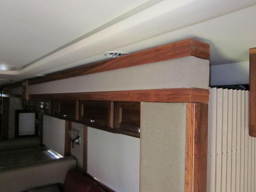
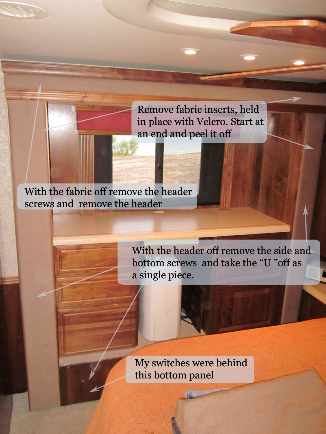
Remove the fabric, its attached to boards that are attached with Velcro to the slide valance. Just start at one end and slowly peel each section off.
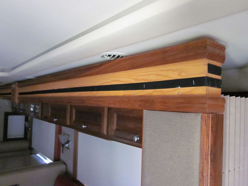
With that done you just remove the visible screws along the top, about a dozen or so, and then with a helper remove the long top valance, its length makes it awkward for one person to handle, plus its got some heft to it as well.
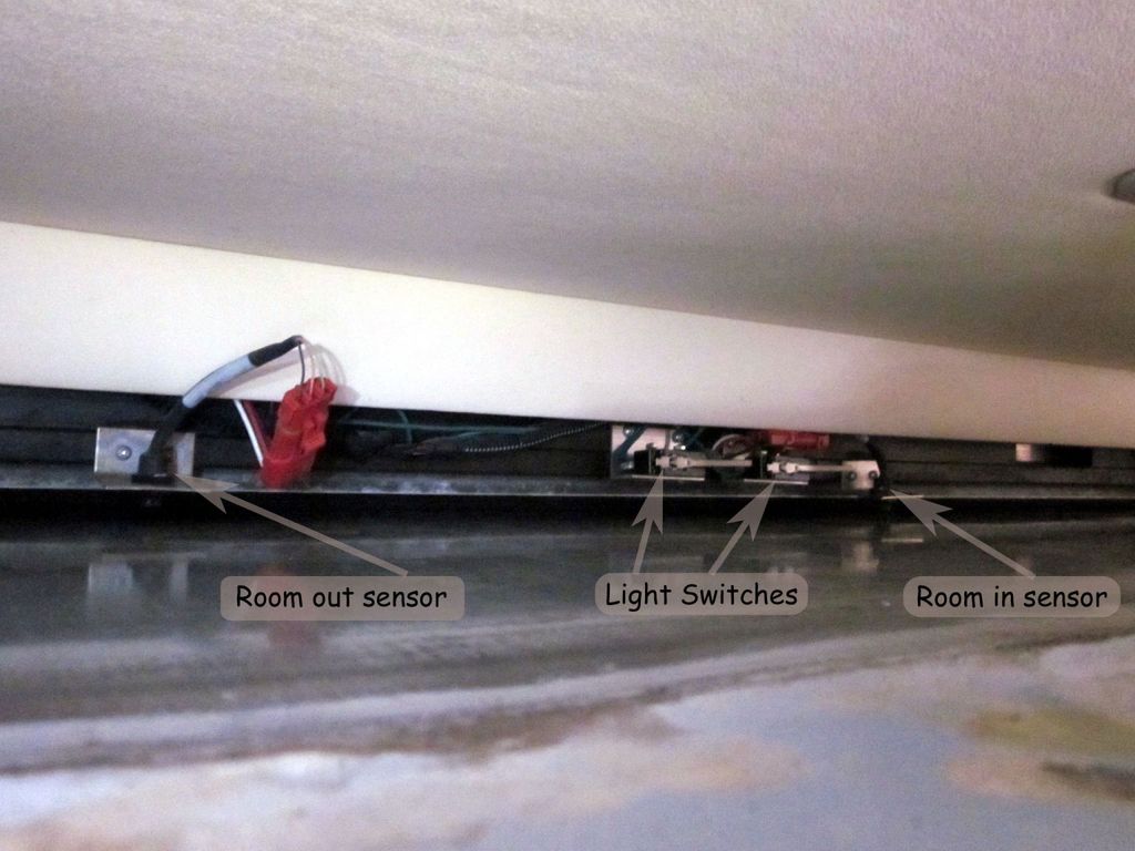
Once its removed you will be able to see and access the switches. In mine there were 4 in all behind the valance, two magnetic reed switches for room in / out status and two mechanical switches to turn off the ceiling halogen lights when the slide is in.
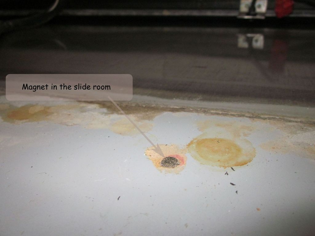
The switches interact with magnets that are embedded in to the slide room, those magnets were still very strong so it would be the sensors that will need replacement at some point. I located the magnets using another small round magnet, I did that just to ensure the sensors were right over the magnets (they were)
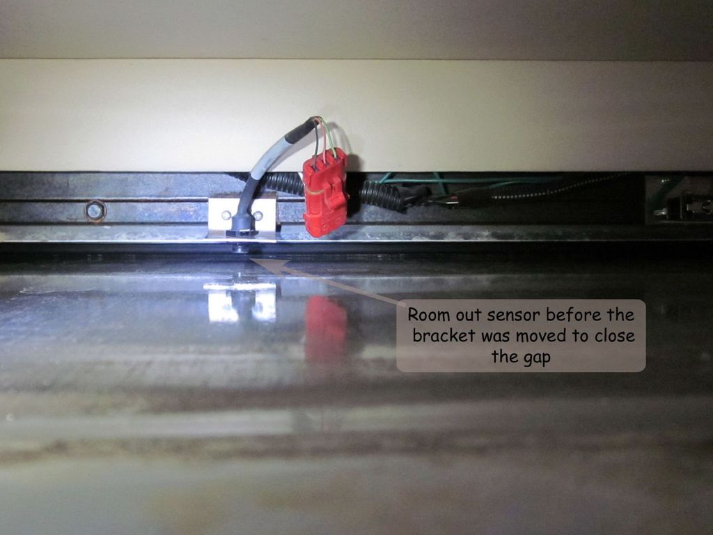
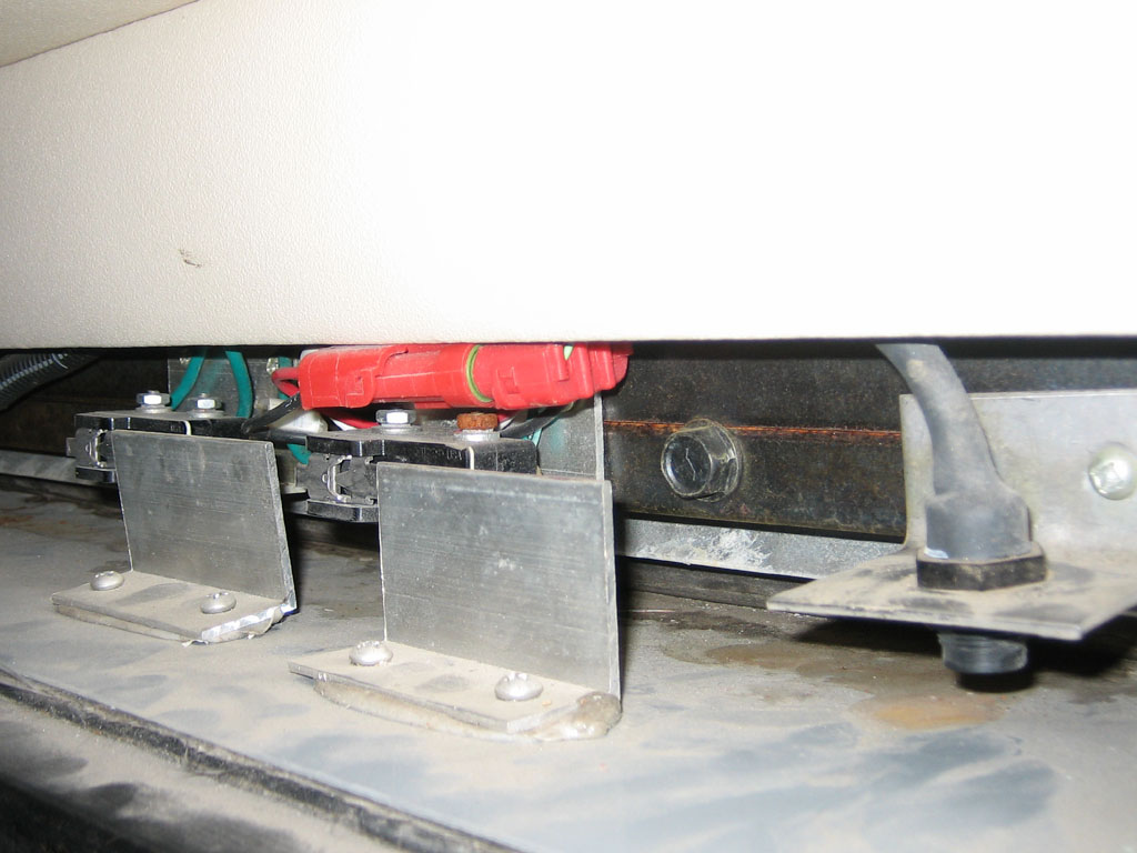
Here is the room out sensor before adjustment, the sensor has a short threaded area and was already set all the way down. I decided to add some new holes to the mounting brackets so I could shift them down closer to the slide. The brackets are made out of stainless so have a good drill bit. I noticed there were a couple of sets of mounting holes in the chassis frame, looks like the brackets were lowered by drilling new holes in the frame once the built in adjustment had been consumed.
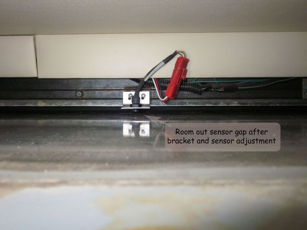
And here is what they looked like after I was done with my adjustments.
The bedroom ones are mounted below the slide, so you need to remove a few extra sections to access them.
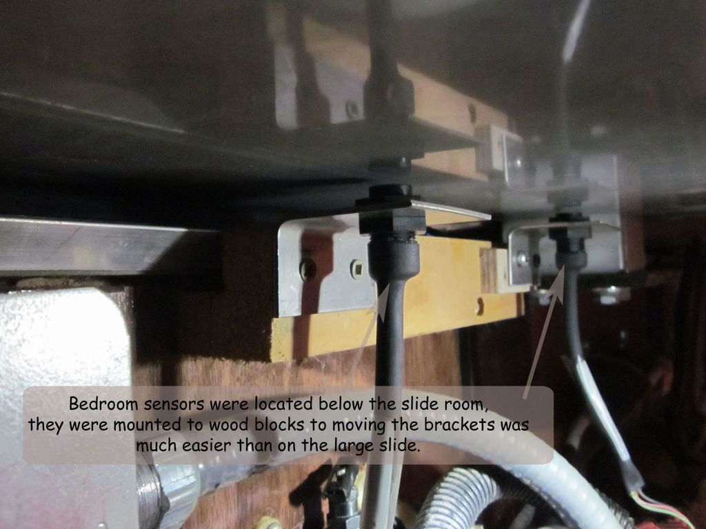
The bedroom ones were mounted to wood blocks to moving those brackets was a breeze, be sure to pre drill those holes or you will split the wood.
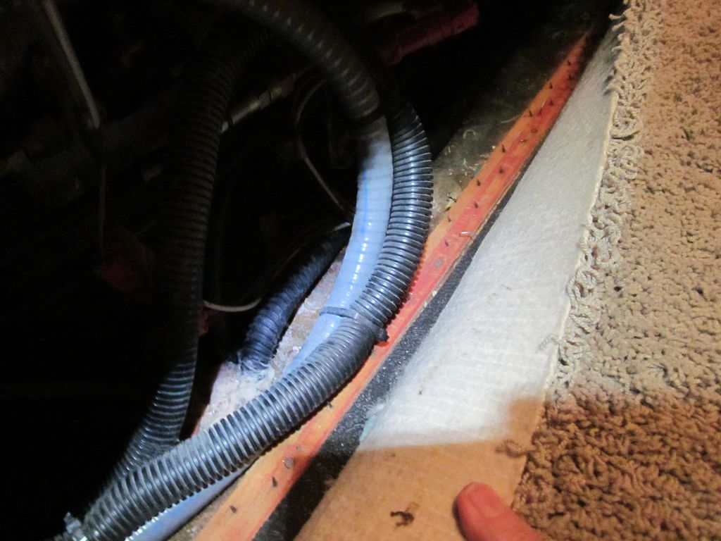
I also found that the control cables and electrical cables had been installed on top of the carpet tact strip. Glad I ended up doing this work before I ended up with a more serious problem due to the lack of care during initial assembly of the coach.