HWH Pump Rebuild
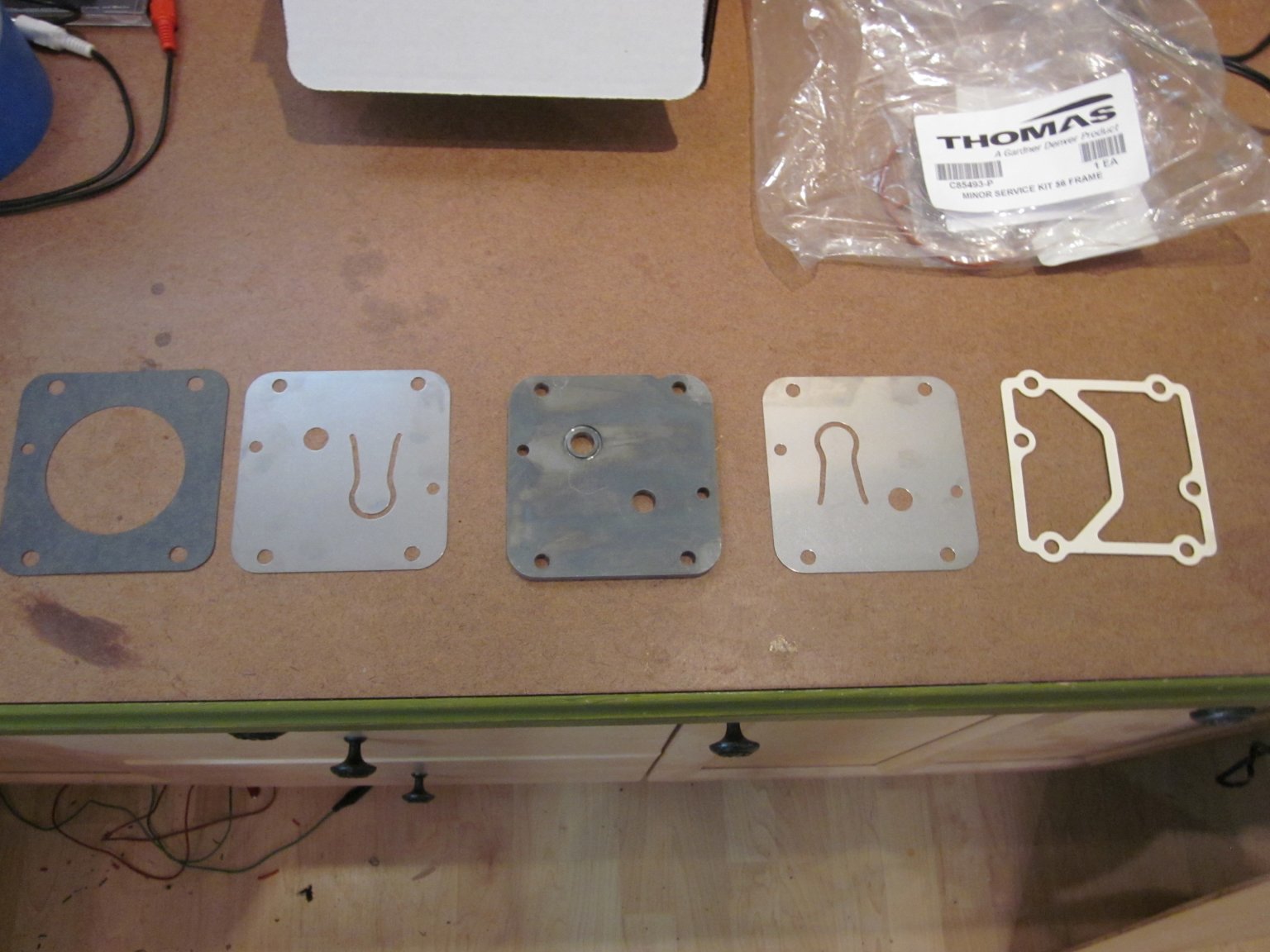
I ordered an HWH minor service kit and set of brushes so I could do a rebuild of the pump to make it “like new”. The minor service kit arrived after a couple of months of waiting. The brushes however have not arrived and the manufacturer does not seem to be in any rush to make any.
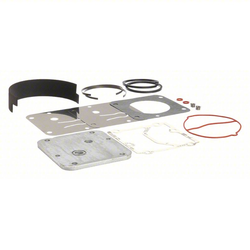
The minor kit is C85493-P and comes with both the VALVE SERVICE KIT C85485-P and RING SERVICE KIT C87860-P, the impossible to get brushes are DC BRUSH KIT C85517.
The recommended service interval for the brushes is 1000-2000 hours and the minor rebuild kit is 6000 hours. I’m sure I don’t have 6000 hours on the pump but I do have some long run intervals where the solenoid valve failed and left the pump running for days.
I purchased the parts from Grainger, the rebuild kit was ~$240 and the brushes ~$60 a pair. You can buy the kit directly from Thomas or even Amazon Do shop around as the price varies significantly between vendors.
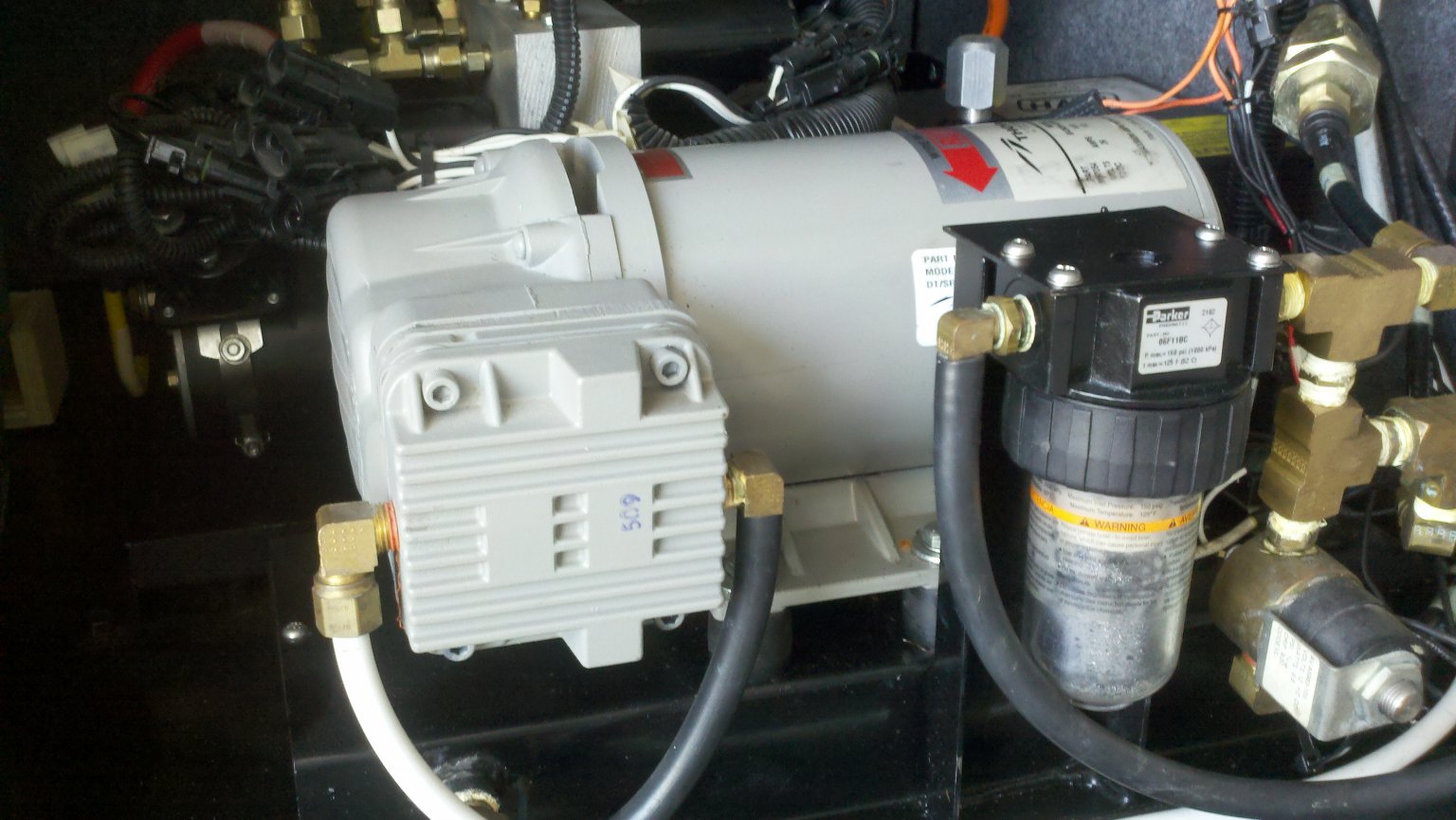
About the Thomas 4101 TA (task air) compressor
Just to be fair to our little Thomas 4101 TA (task air) compressor:
- In a slightly different configuration it is named Ready-Air which is a good enough for use in Turtle Expedition.
- It is the same unit as used in the Hummer’s Central Tire Inflation System (CTIS).
- Can be found on Ebay from time to time in the $250 range. (Just checked and one recently sold for $105 NIB!)
So its a really a rugged little compressor, rated for continuous duty, permanently lubricated and sealed bearings, cast iron cylinder, stainless steel reed valves, PTFE piston rings and skirts. The recommended minor rebuild is at 6000 hrs of continuous duty or with a 33% duty cycle in two years … For my duty cycle its about 25 years. (even though I did do the minor rebuild at 10 years since it was fun and gave me an opportunity to take it apart)
So let’s dive in!
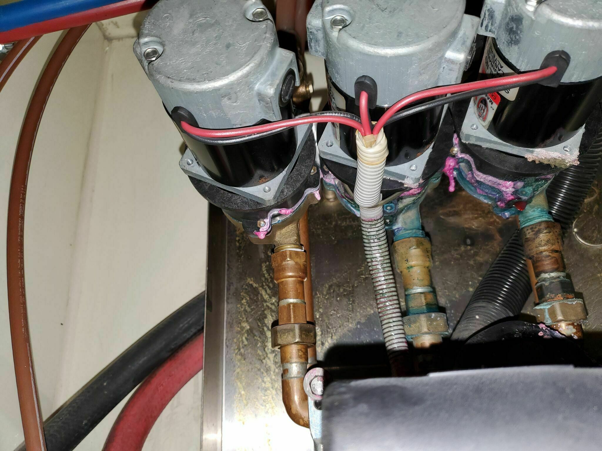
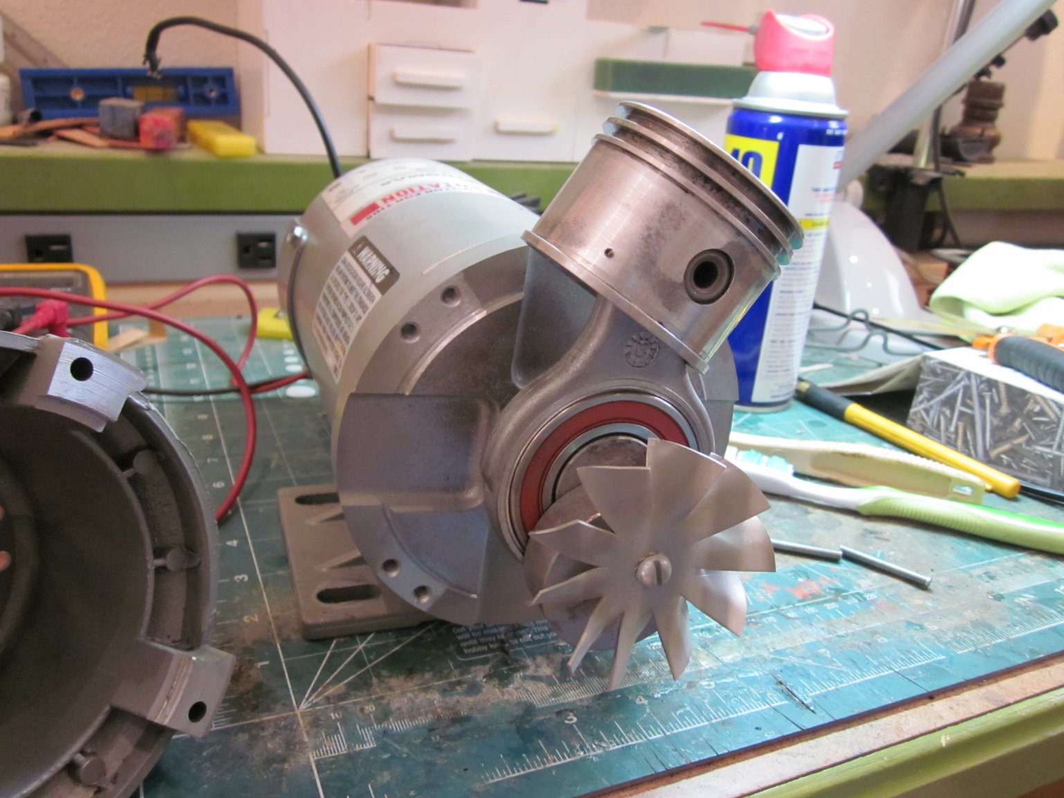
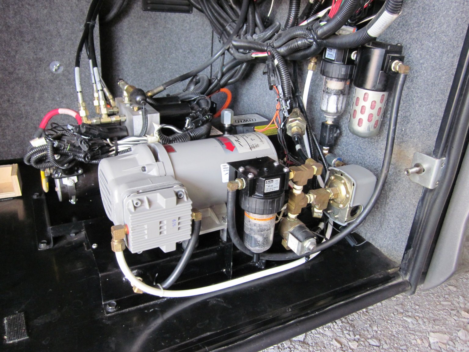
First up is remove power from the pump; just undo the +/- leads from the end. I pulled the fuse and checked for power before I did anything. One important note, those end lugs on the motor, where the +/- leads attach, pass straight though the motor’s end casing and have the brushes attached on the other side. Make sure that only the nut is turning and not the lug shaft or you could damage the brush leads.
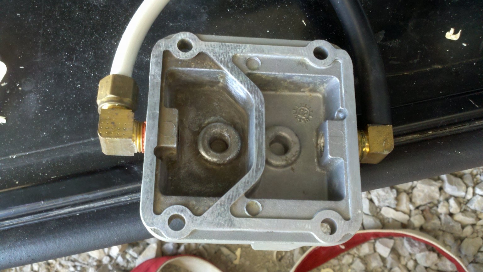
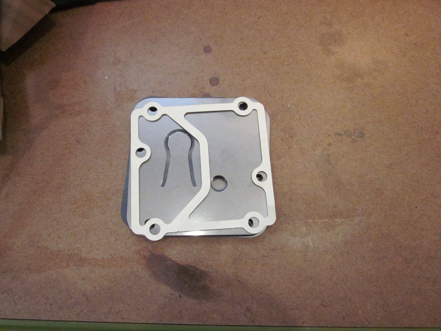
Now remove the 4 cap head screws from the cylinder head, they hold and clamp the piston sleeve, reed valves (2), valve seat (1) and cylinder head in place. Once removed, the cast aluminum cylinder head comes right off with the valve reeds and seat. Leave the piston sleeve in place for now.
The valve reeds are stainless steel and are dry fit to the valve body. The outsides of the reeds have gaskets to seal them to the cylinder head and piston sleeve flange. Separating the valve reeds from the gaskets was easy, however the gasket to cylinder head was difficult. It was a thick white gasket that was very dry and very tough.
You have to gently scrape it off, making sure not to damage the sealing surface on the cylinder head. I used a scraper and razor blade; took a while but it does come off. If you have a later model of this pump, you might be lucky and have an O-Ring gasket instead, both a replacement O-Ring gasket and paper gasket are include in the kit, you just use the one that fits your era pump.
After that gasket was removed I cleaned up the inside of the exhaust (compression) side of the cylinder head, nothing fancy here just lightly rub down the inside of to remove the build up.
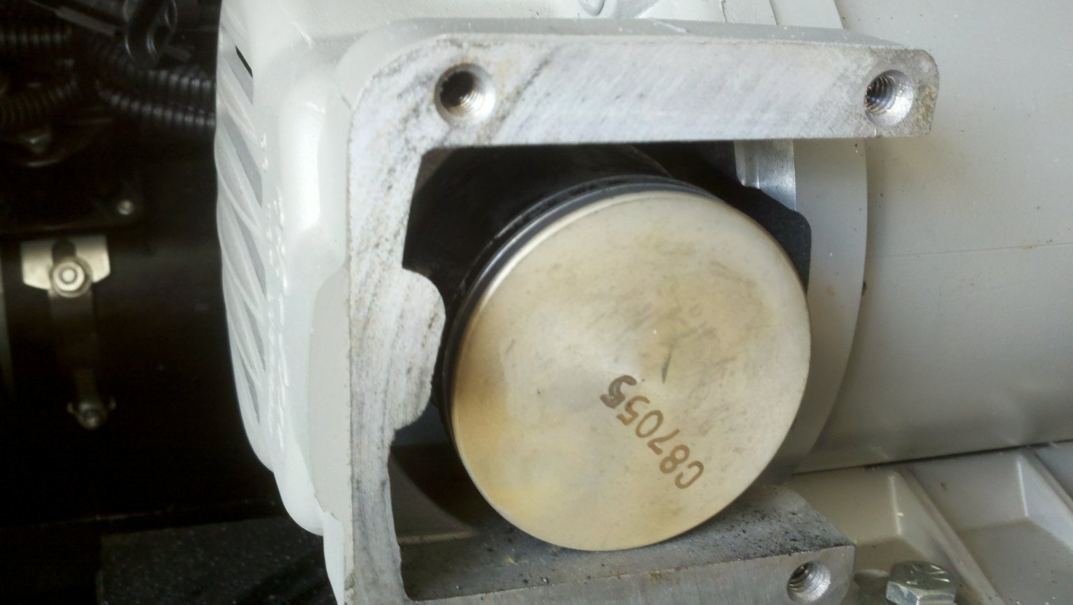
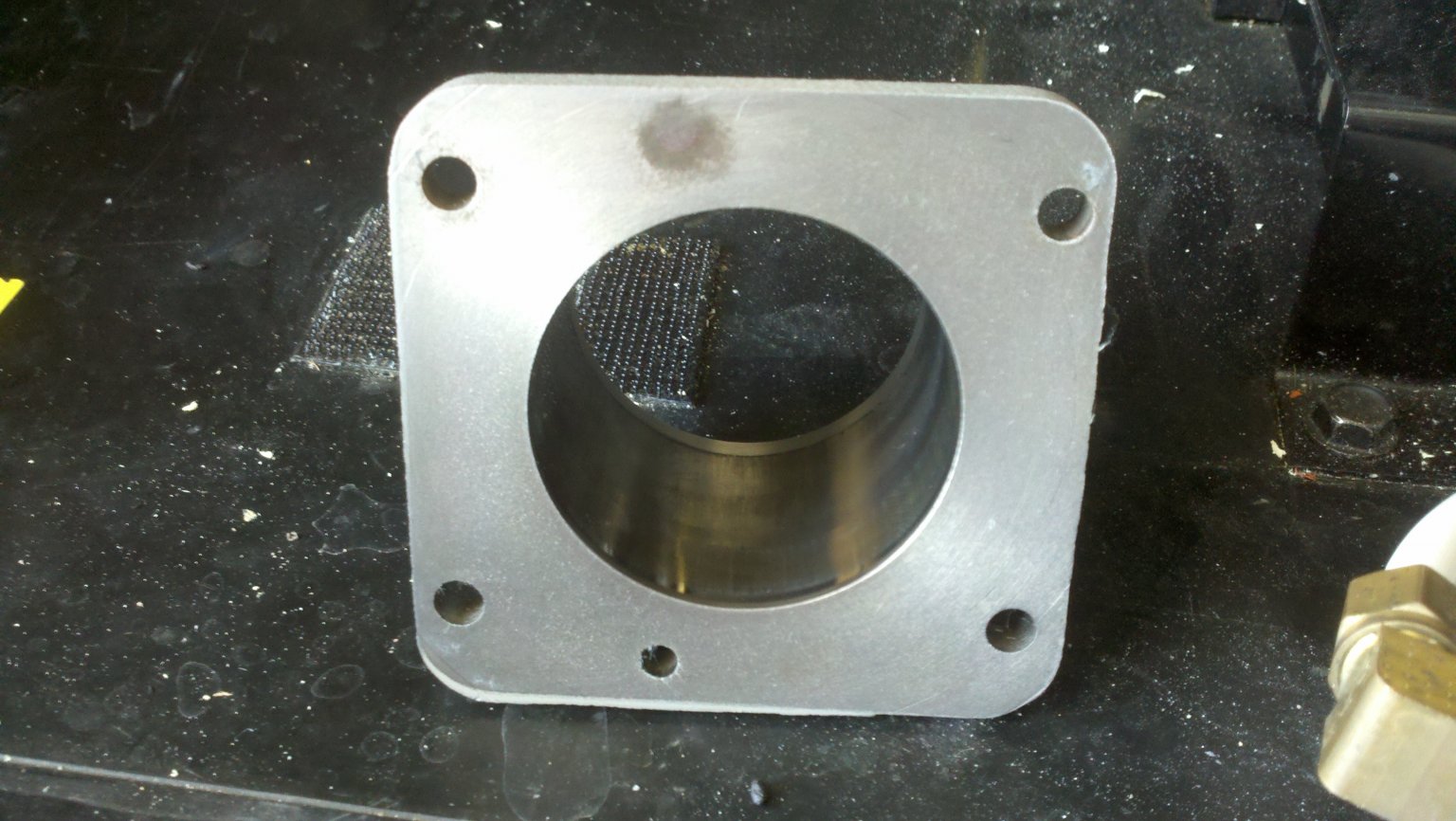
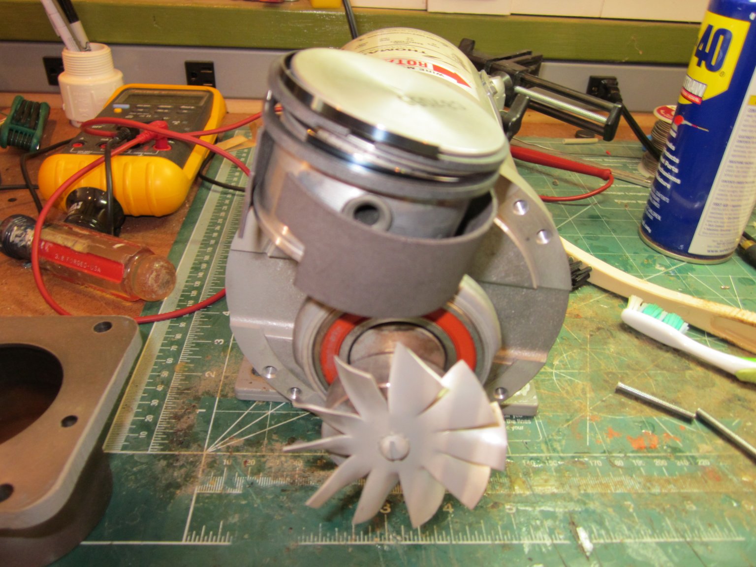
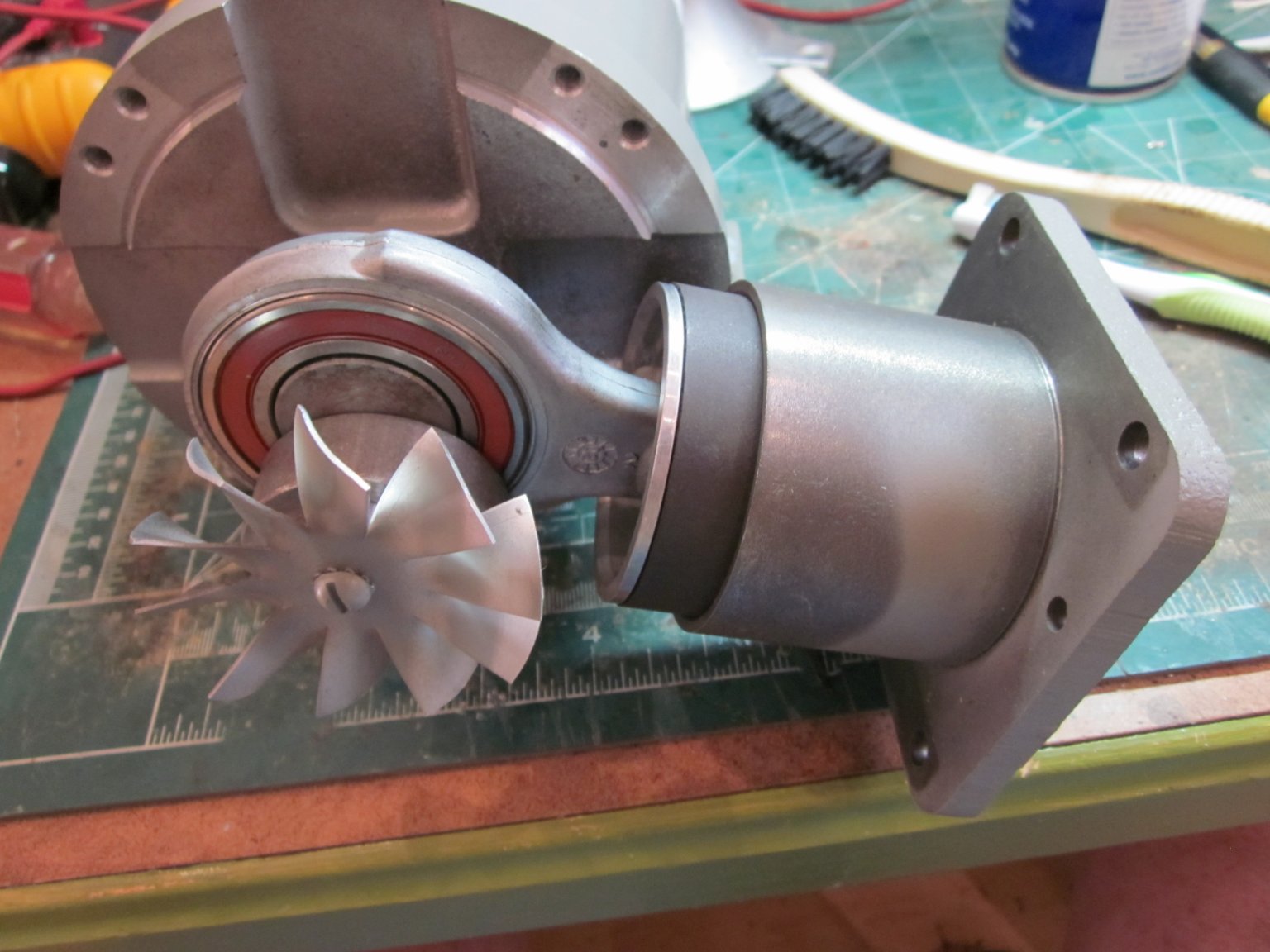
Up next was to remove the cylinder sleeve, it slides right off the piston. Make sure you do not let the piston “bump” into anything by supporting it from behind as the sleeve slides off. The inside of the piston sleeve had a fair amount of buildup, I cleaned this surface with a cotton rag and water. You do not want to get any cleaning contaminants or hone this sleeve, remember it’s a dry running air cylinder and piston. With the piston sleeve out of the way the rings, springs and skirt can be easily removed from the piston.
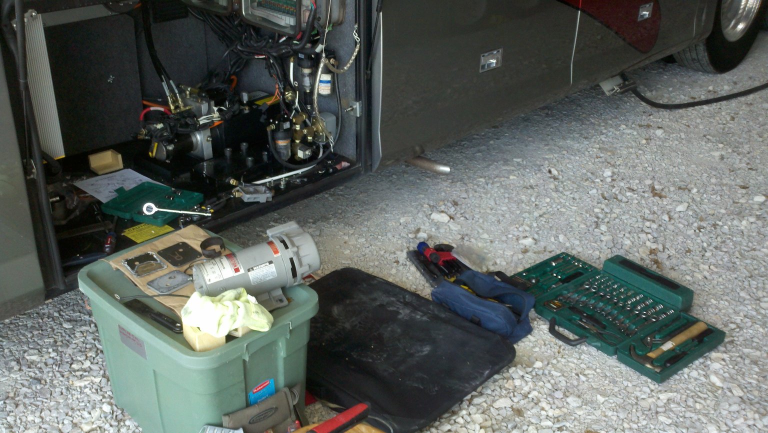
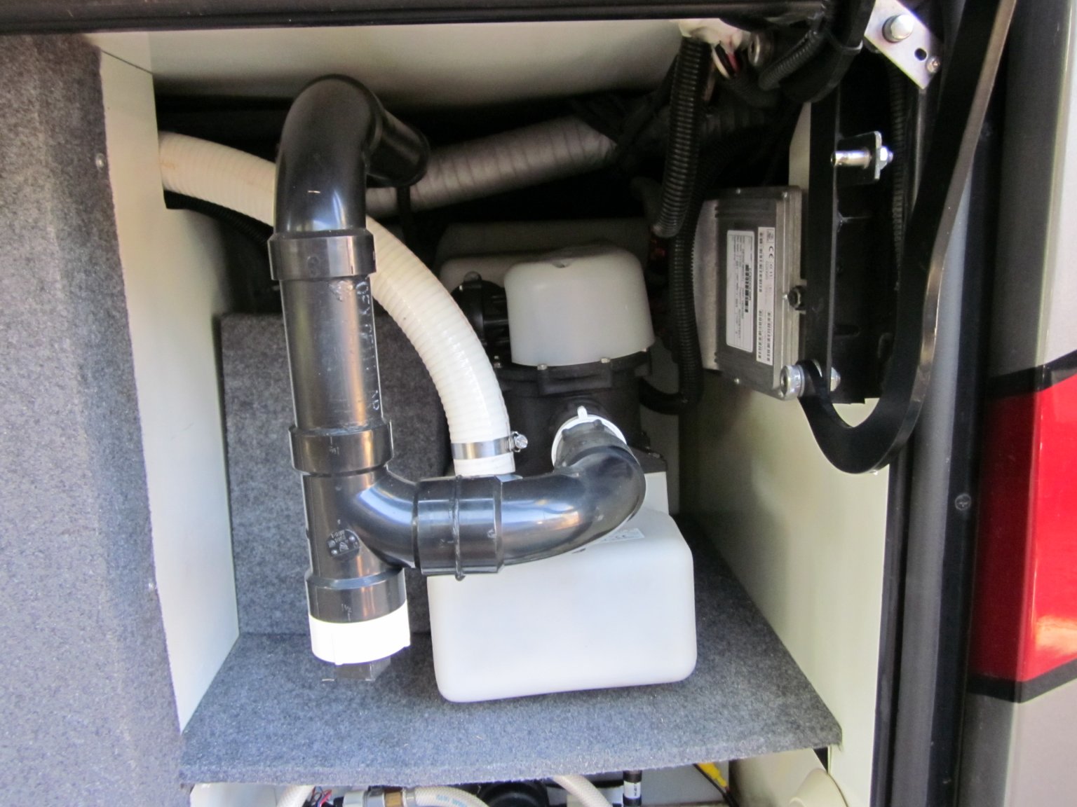
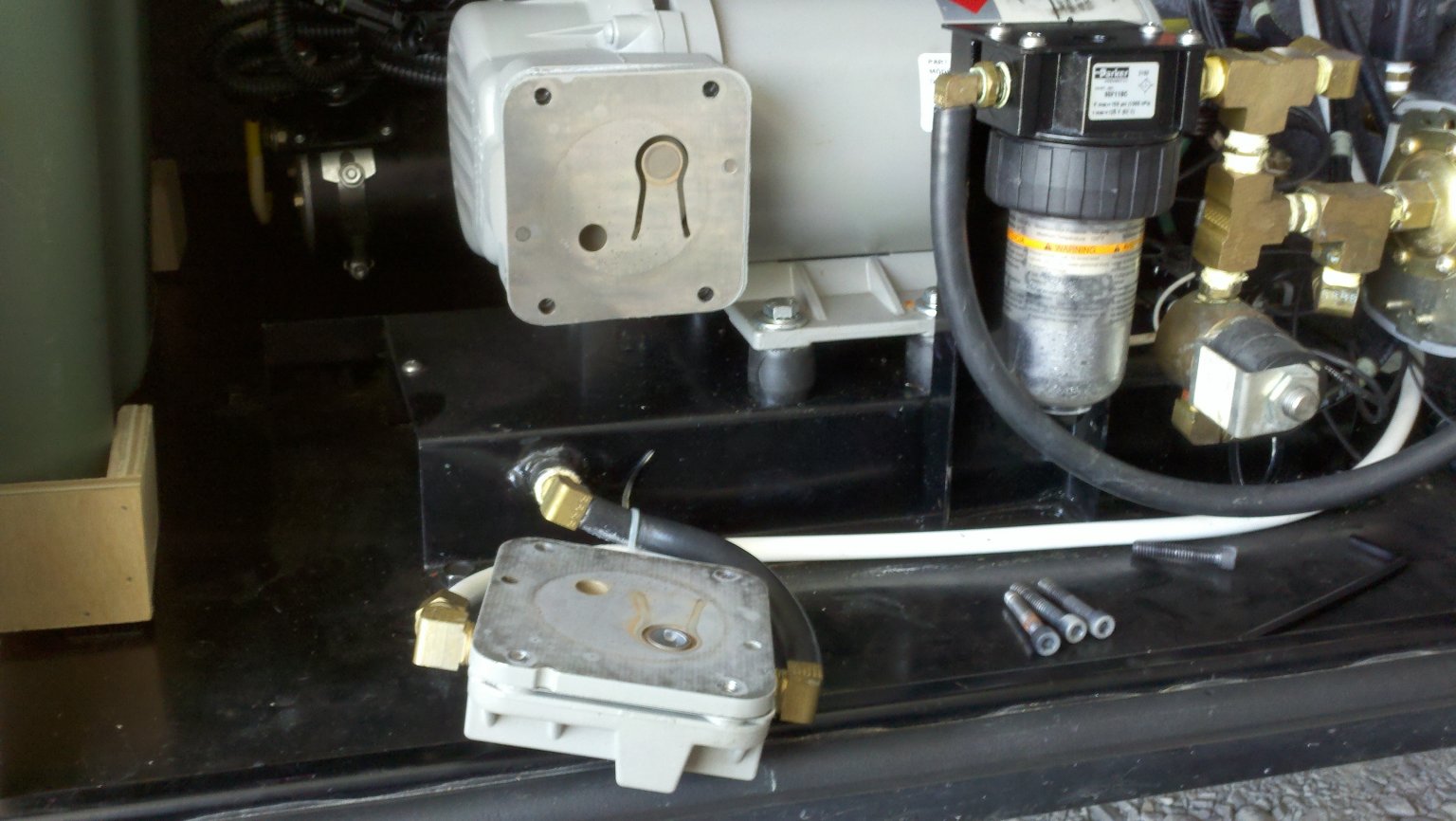
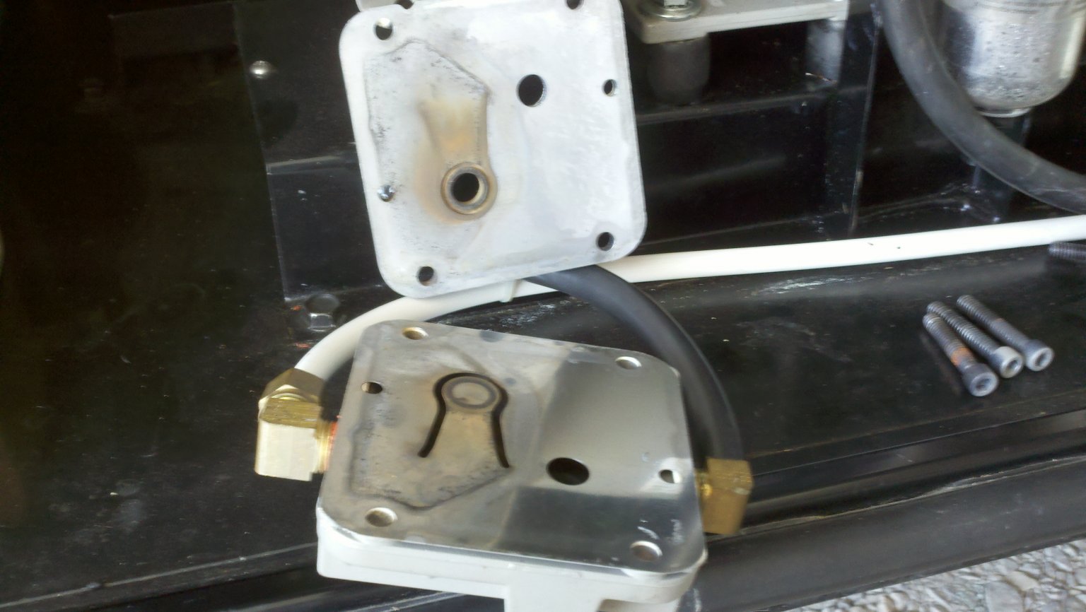
At this point in order to gain access to clean the cylinder ring grooves and to be able to hold the new rings in place while the piston sleeve is slide back on, you need to remove the crankcase cover. It covers the motor output, crank and piston rod. In my case it was inexplicably secured with 4 slot head screws. The exploded diagram shows cap head but that’s not what mine were. Those screws were not going to budge before the heads deformed, you could just not keep the screwdriver from twisting out. At this point I had to remove the pump from the bay so I could get better access to those 4 screws. The only thing holding it in place were the 4 bolts that secure it to the vibration isolators.
With the pump on the bench I had access to the back of the screws so a little Liquid Wrench was applied and allowed to sit overnight. The next morning those screws would still not release. Screwdriver, secured down in the slot and a wrench, no luck, a touch of heat to the thread ring, no luck, some heat to the screw heads, no luck. Eventually I was able to convince two of the 4 to loosen. The other two had other ideas, as did I. Off to the endmill and off with their heads! (Make sure you cover all the motor/pump openings should you resort to this). Ok Really I took them down to within a few thousands or so, just a thin disc left which I removed with a fine file. Then the cover slide right off and the remainder of the screws came out by hand. The screws were painted in place so I don’t know if some paint got between the head and the cover, or some reaction occurred between the paint, steel and aluminum casing, but they were well stuck in place.
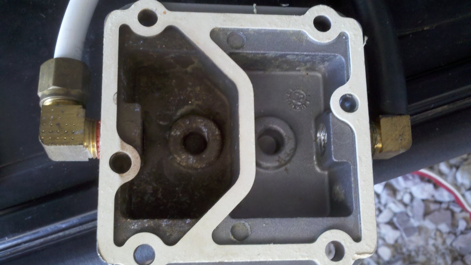
OK back on task, I cleaned the piston ring grooves and put the new springs and rings in place in those grooves. The springs are flat springs which go in first and then the ring is concentrically placed on top the the spring. The spring serves to “press” the ring against the cylinder wall. There are two rings in this setup, be sure to stagger the splits in the rings so they are not in-line with one another. The spring pressure is very low so you can just hold them down in the piston ring grooves while you slide the piston cylinder over the rings. Once the rings are held in place, place the piston skirt gasket in place and finish sliding the cylinder all the way down.
Now replace the crankcase cover, and yes I used cap-head screws instead of the “standard” slot heads. Then assemble your gasket/valve stack gasket-reed-valve body-reed-gasket-cylinder head stack-up and screw it down though the piston sleeve flange and on to the crankcase cover. Then remount it to the isolators, and reattach the +/- leads.
Turn it back on and enjoy the improved pump (pump up time and somewhat lower noise)