Adding a RPI Touchscreen Display
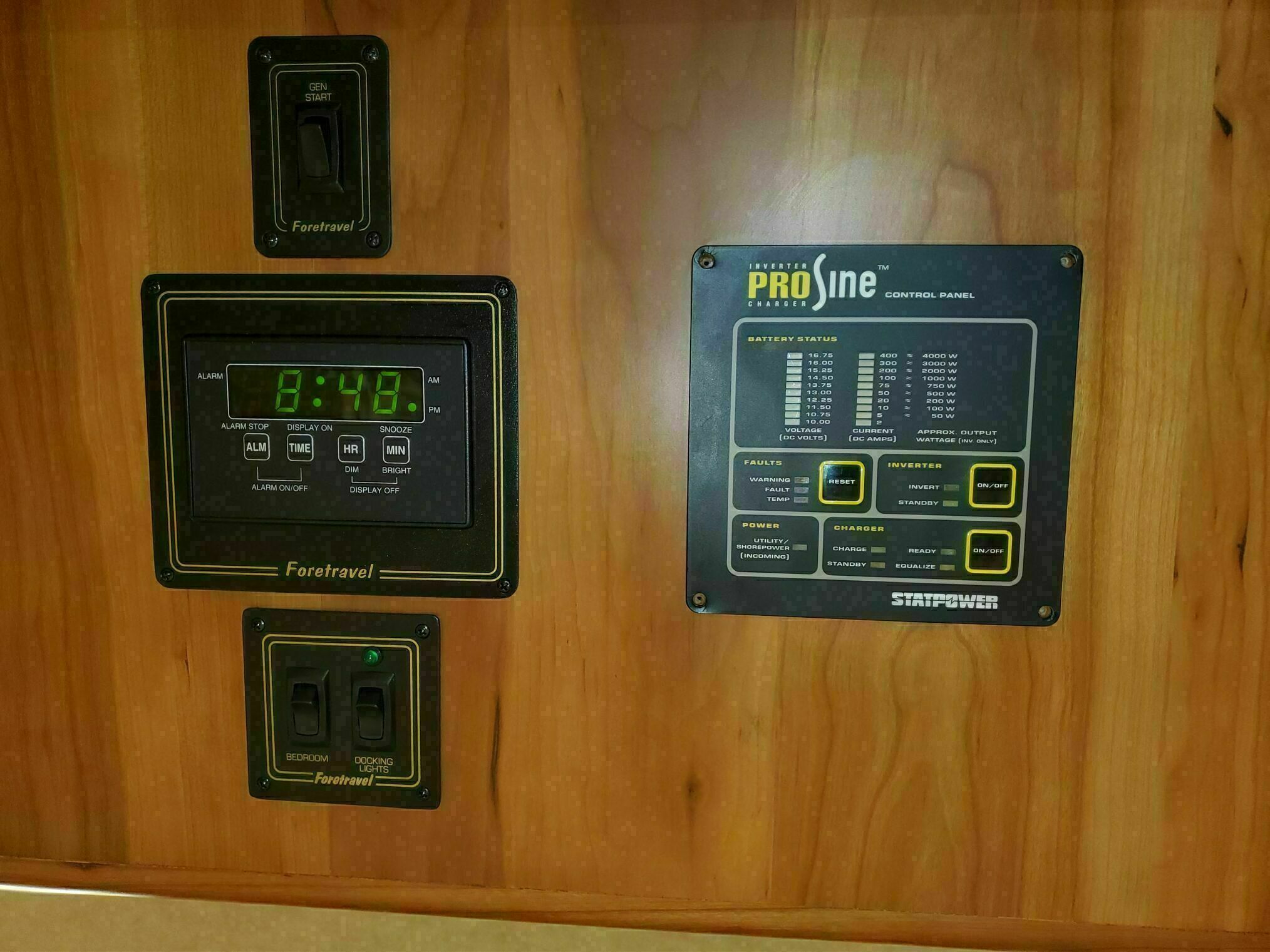
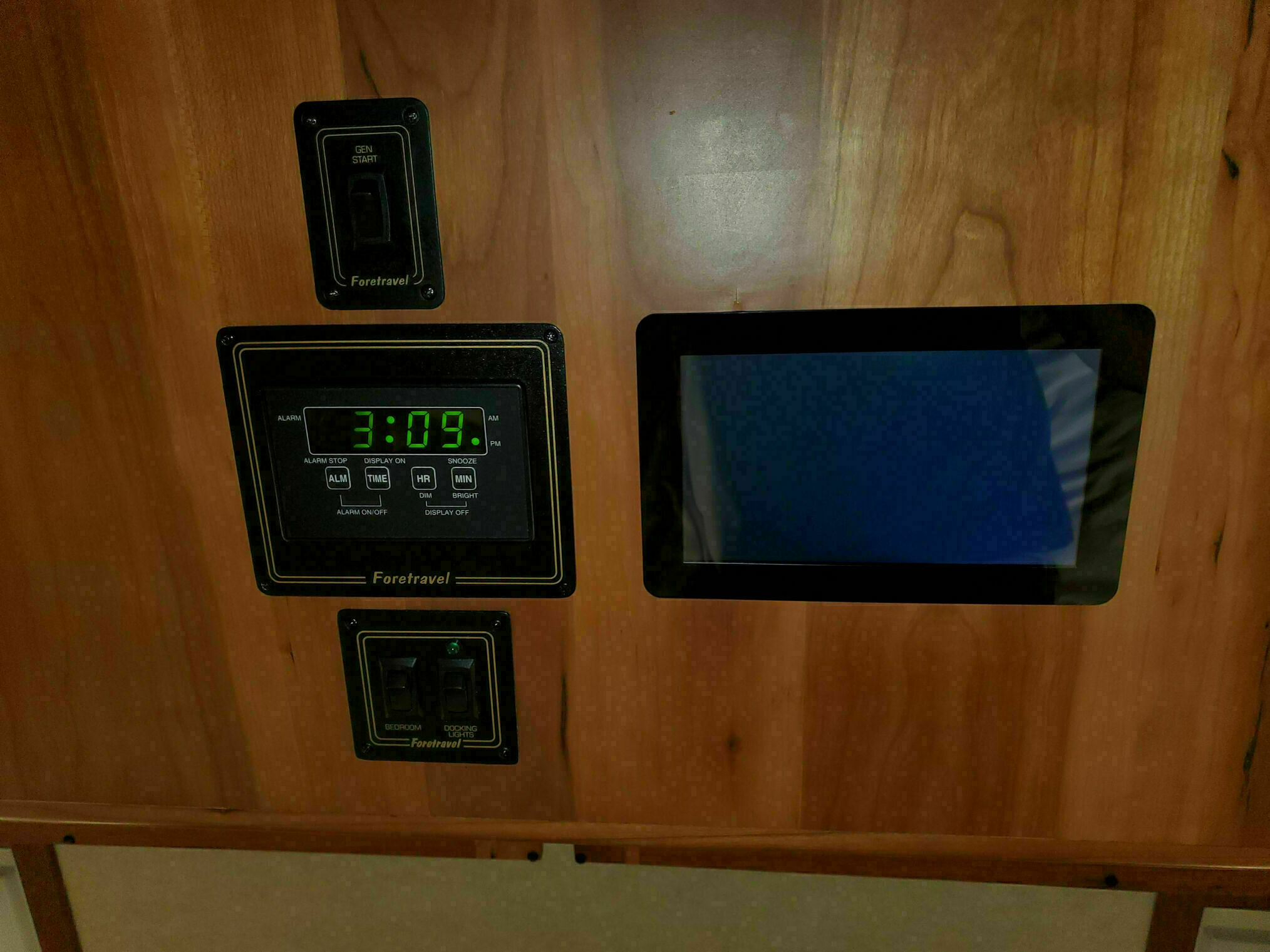
One of the first upgrades we tackled was replacing the ProSine control and readout panel that had been installed above the bed, right next to the clock, generator start switch, docking light switch, and other controls.

If you’re thinking that’s a strange place for that panel, you’re not wrong. At night, the LEDs were bright and occasionally blinked or pulsed, not exactly conducive to sleep. The previous owner had even warned us that “those lights were something.” That’s an actual recording from my first morning after trying to sleep under them.
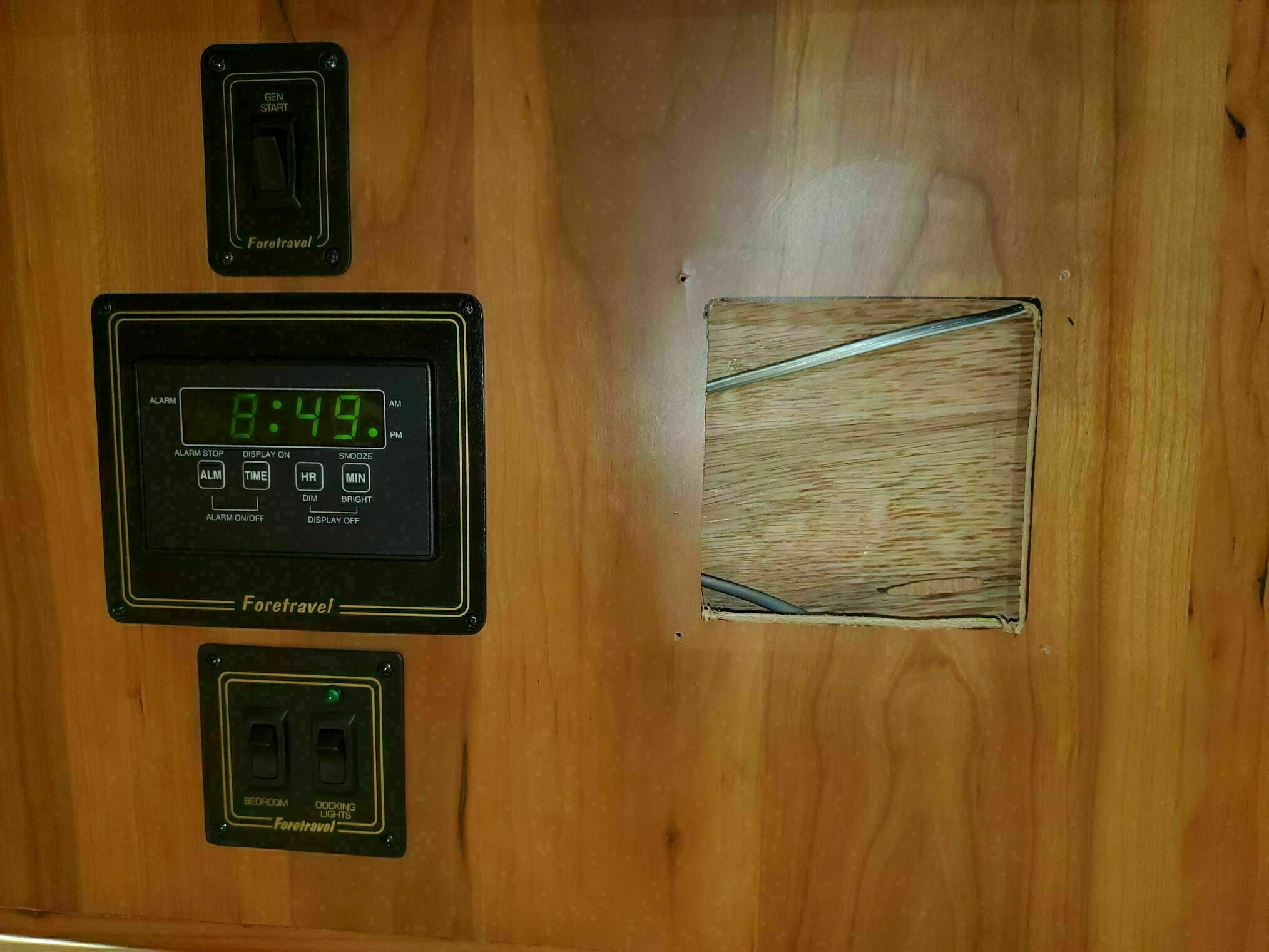
Once we completed the Victron installation, the panel’s lights were no longer active, but leaving an empty, obsolete panel behind wasn’t an option. Simply patching over the opening would have looked exactly like what it was—a patch job. So I started thinking about what could replace it, and that thought process ultimately led to this entire automation project.
Installing the Touchscreen
We removed the old ProSine panel and replaced it with a 7-inch touchscreen. Like most of the cabinetry in our coach, there was about one inch of available depth behind the surface. The original cutout needed to be enlarged slightly to accommodate the new display, so I carefully expanded it using an oscillating multi-tool. I made sure to tape off the area first—that veneer is surprisingly brittle and chips easily.
For the display itself, we chose the Raspberry Pi Touch Display 2. Its bezel is wide enough to mount securely using narrow 10mm VHB tape around the edges. The panel includes four mounting bosses on the back, and my initial plan was to use a custom bracket to clamp it in place. That approach turned out to be a mistake! Even light clamping pressure caused the back of the display to separate from the screen.
In the installation photo, you’ll notice the brackets are now positioned upside down. They were only there to help position the display correctly while I pressed the VHB tape firmly against the cabinet surface.
Power and the Raspberry Pi
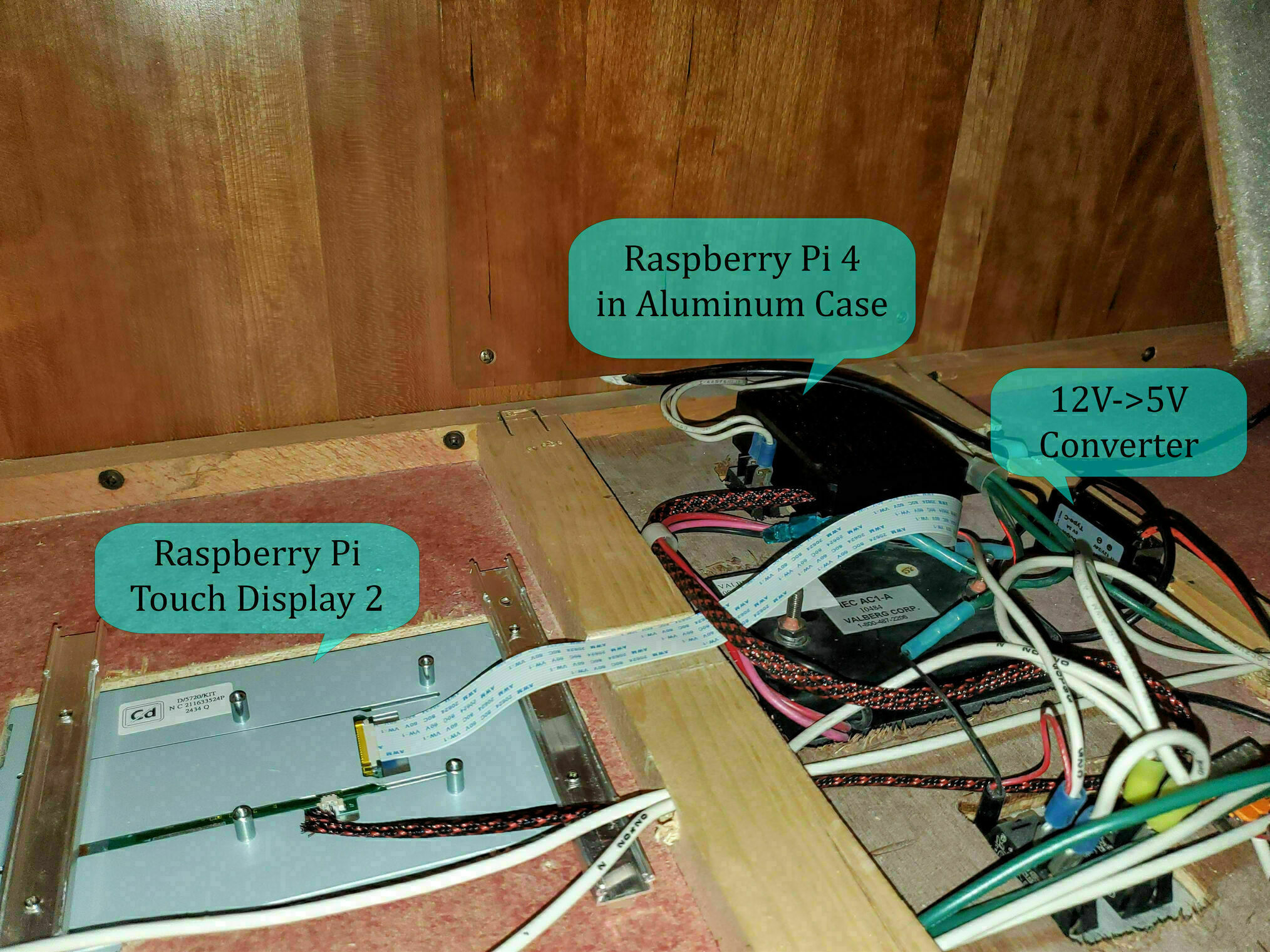
A touchscreen isn’t particularly useful without something to drive it. I initially wanted to use a Raspberry Pi A+ since its compact form factor would allow it to mount directly behind the display and still fit within that limited 1-inch cabinet space. Unfortunately, its limited memory made running a graphical interface far too sluggish for practical use. Instead, I switched to a Raspberry Pi 4 Model B that I already had on hand.
The Pi is installed in an aluminum heatsink case under the access hump in the center of the cabinet, the same area where the clock and switch wiring runs, since it’s too thick to fit in that 1-inch space behind the display. Power comes from a 12V to 5V DC-DC converter, and I used a longer display cable since the one included with the touchscreen was far too short to reach. The display draws its power directly from the Pi’s GPIO pins.
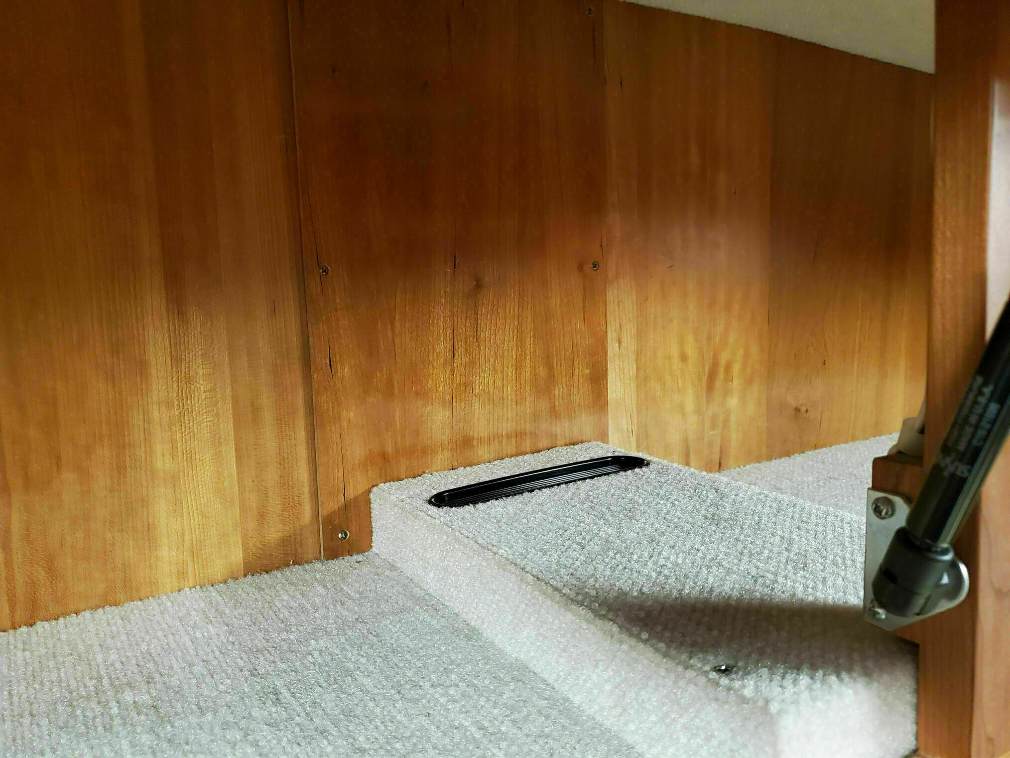
To help with cooling, I added a small vent at the rear of the hump to improve airflow. With this passive cooling setup, the CPU typically runs around 100°F, staying nice and cool even during extended use.
Software Configuration
With the hardware installed, I loaded Raspberry Pi OS and configured it to run in kiosk mode using TouchKio, which integrates seamlessly with Home Assistant. I’m also using an X-server-based screensaver to manage display sleep.
I initially tried using the default Wayland compositor, but no matter what settings I adjusted, the first touch after the display woke would be passed through to the user interface. This meant accidentally triggering buttons when all I wanted to do was wake the screen. With the X-based approach, I can properly capture the wake touch event, so it simply wakes the display without triggering any unintended actions.
Home Assistant Dashboards
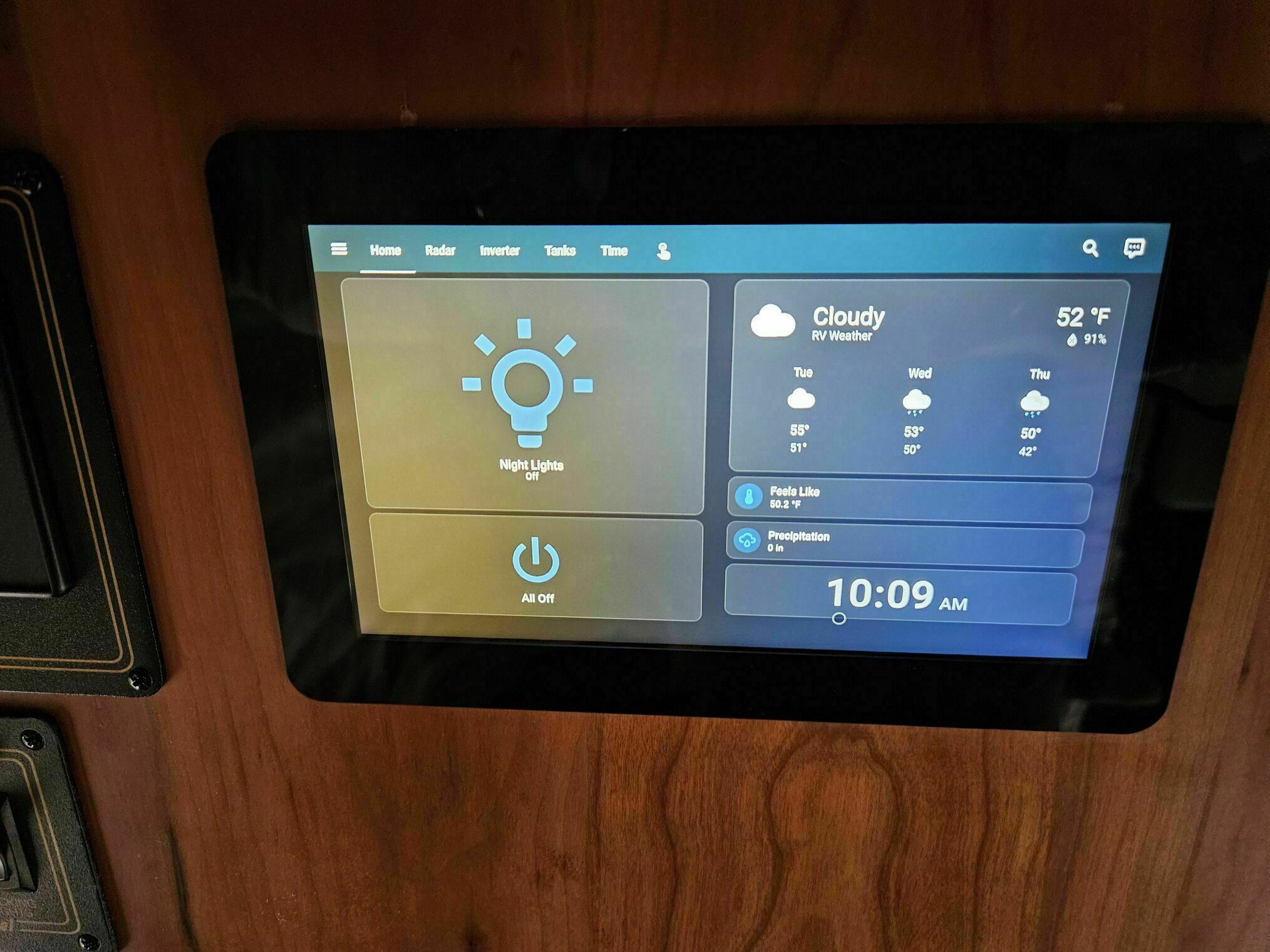
I configured several Home Assistant dashboard views to be accessible on the touchscreen:
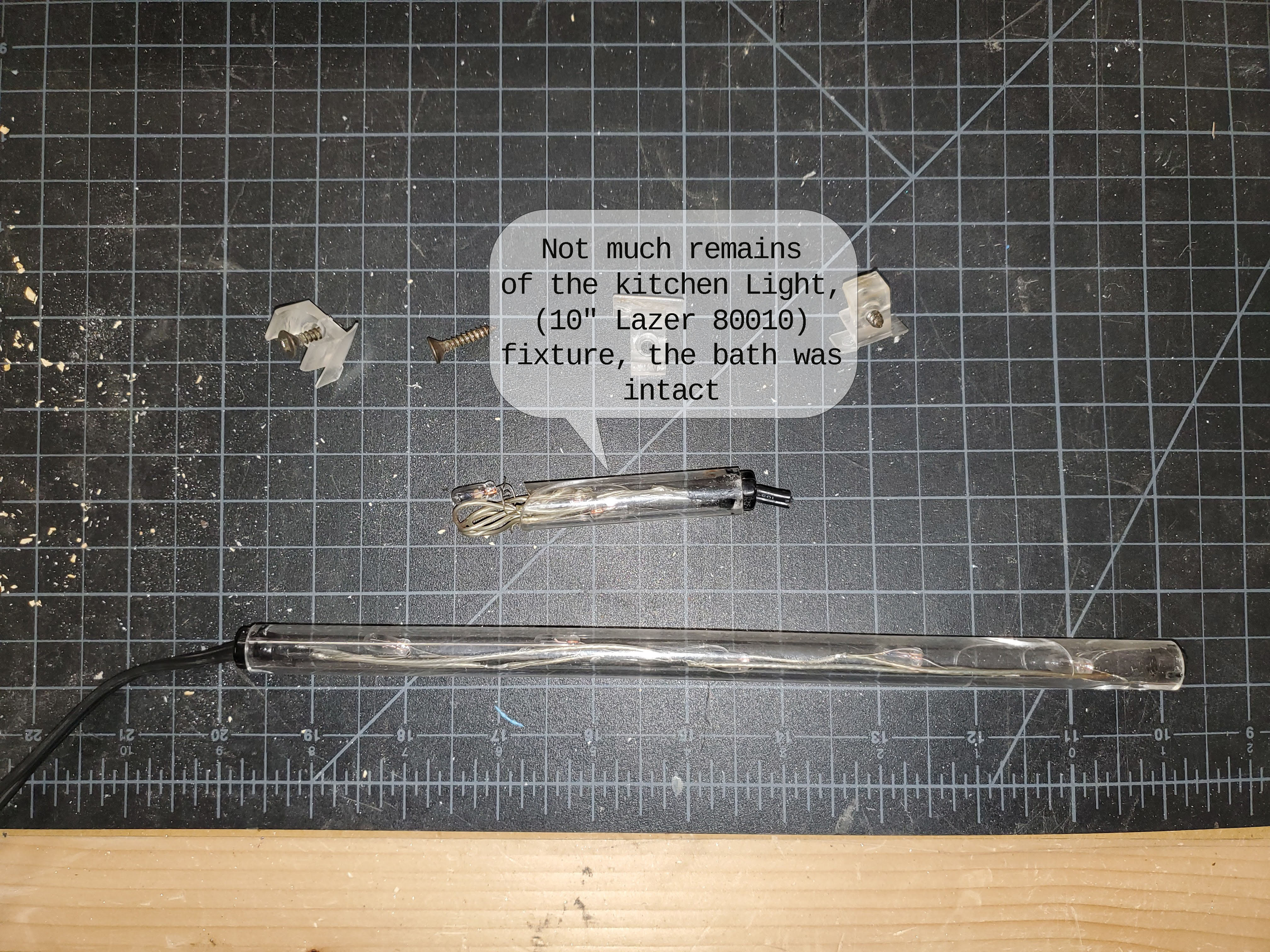
Home Screen: Features “All Off” and “Night Light” controls for those late-night trips to the kitchen without stepping on the dog, along with current time and weather information.
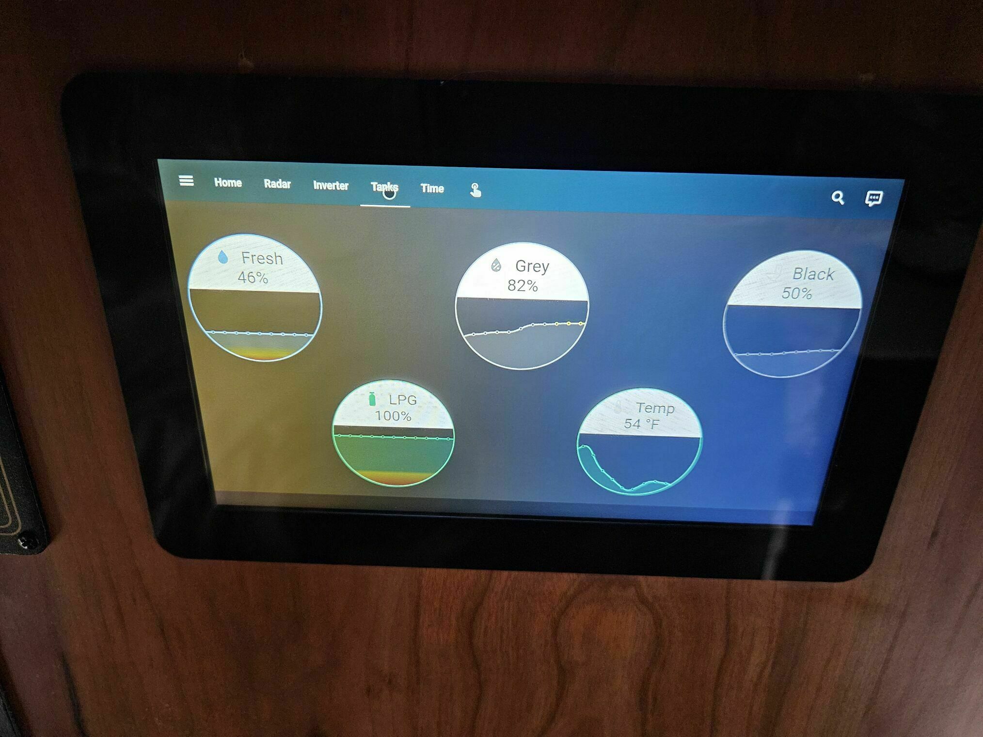
Tank Levels: I enabled MQTT access on the Victron Cerbo, and there’s a Home Assistant add-on that retrieves nearly all the information available from the Cerbo via MQTT. This view displays fresh water, grey water, sewage, and propane levels. The Cerbo obtains these values from the N2K version of the SeeLevel system and the propane tank level input.
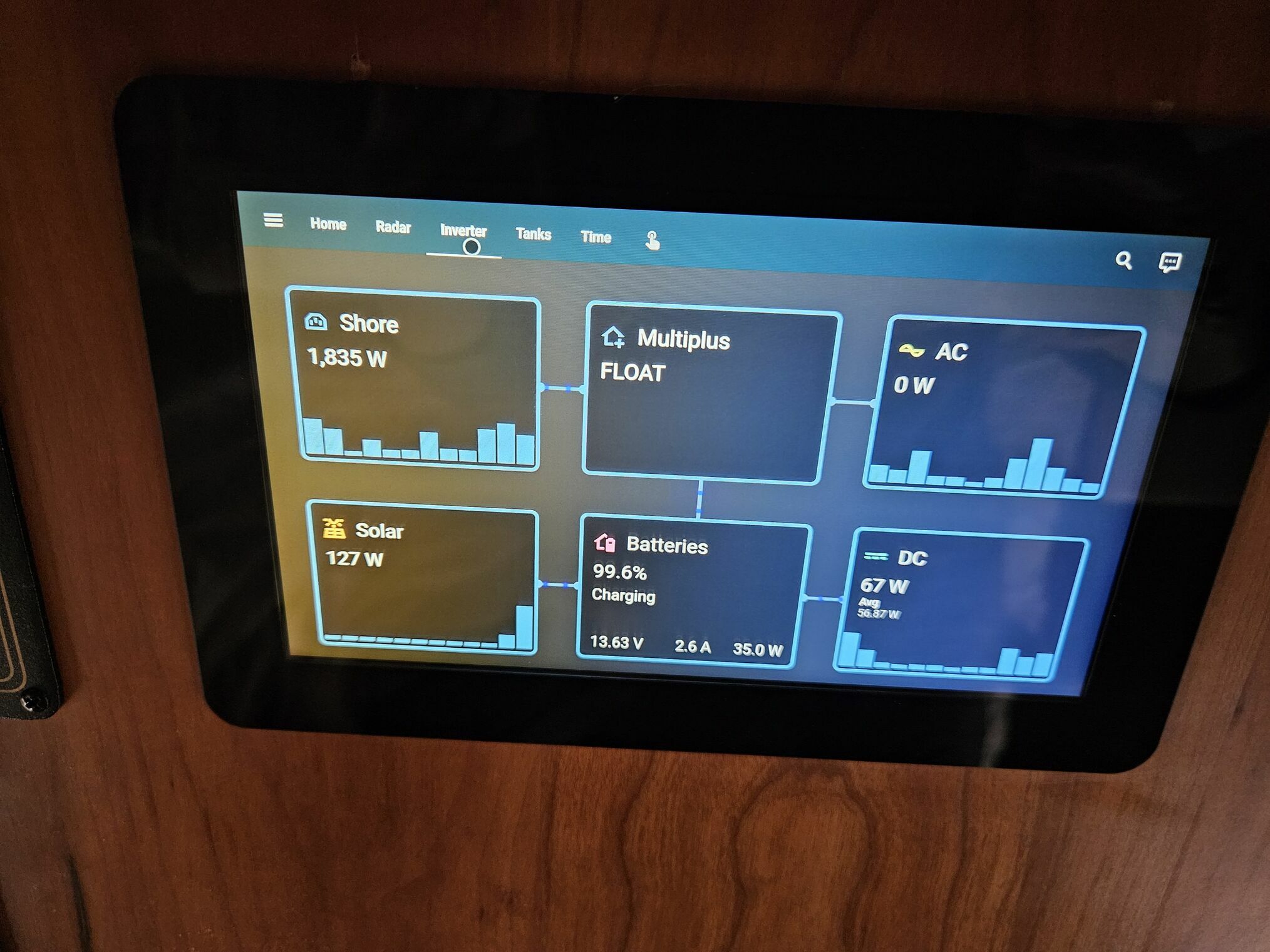
Victron Status: A summary view similar to what appears on the Cerbo display, pulling all values via MQTT.
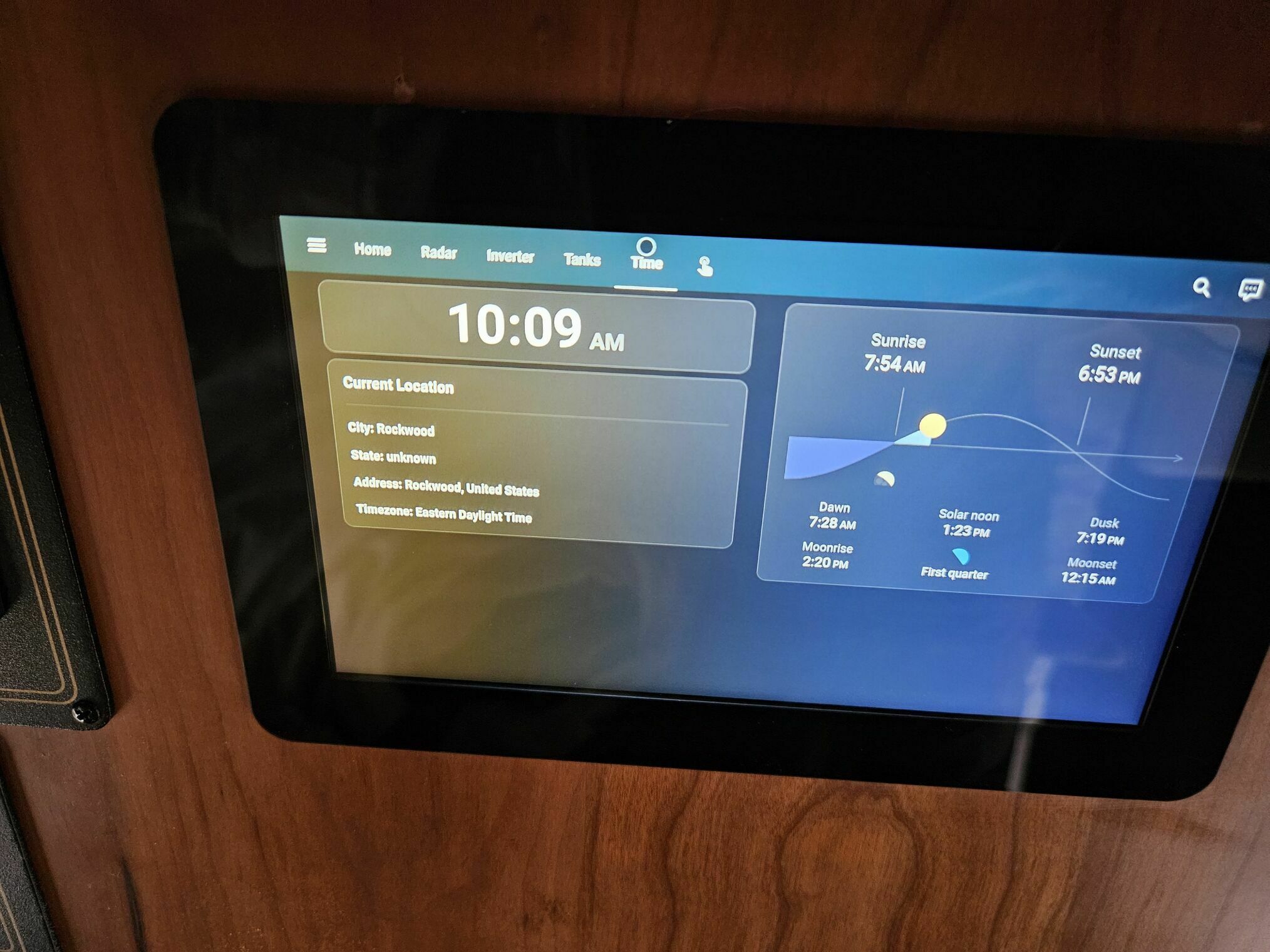
Current Time and Location: Automatically updates based on GPS-derived time zone and location data.
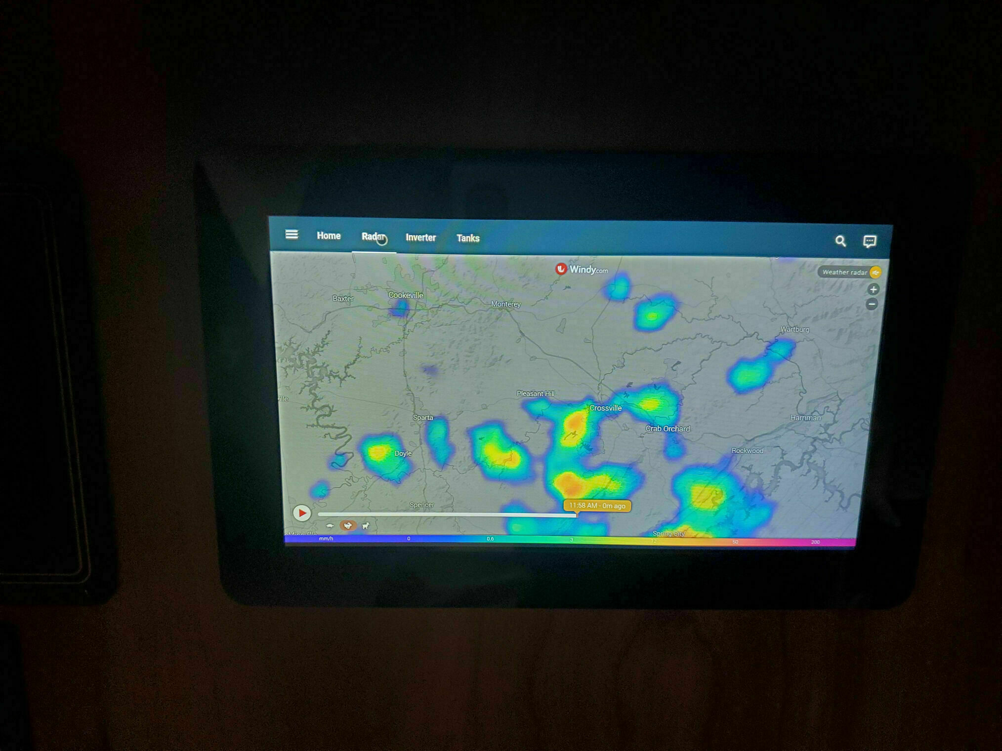
Weather Radar: Auto-updates based on current GPS coordinates. Windy’s API allows you to build URLs with latitude and longitude parameters, making it perfect for this application.
GPS Integration
You can retrieve GPS coordinates in several ways. In my current setup, I have a USB GPS antenna connected to the Cerbo, which allows the device to display our location directly on the VRM portal.
Using Node-RED on the Cerbo, we’re running Venus OS Large to access this functionality, I publish GPS values so they can also be consumed by Home Assistant. GPS data is one of the few parameters that the Cerbo integration doesn’t make available to Home Assistant. Unlike tank levels and other metrics, you need to publish the GPS values manually.
The Node-RED flow to achieve this is straightforward. It updates the coordinates every 30 minutes or whenever our location changes by more than 5 miles, then publishes those values via MQTT for Home Assistant to consume.
Final Thoughts
The change from annoying blinking LEDs to a functional, information touchscreen has been a satisfying upgrad. Not only does it look cool and integrated, but it provides genuinely useful information at a glance. The best part? No more being woken up by flashing lights in the middle of the night.