Toe Kick and Counter LED lights
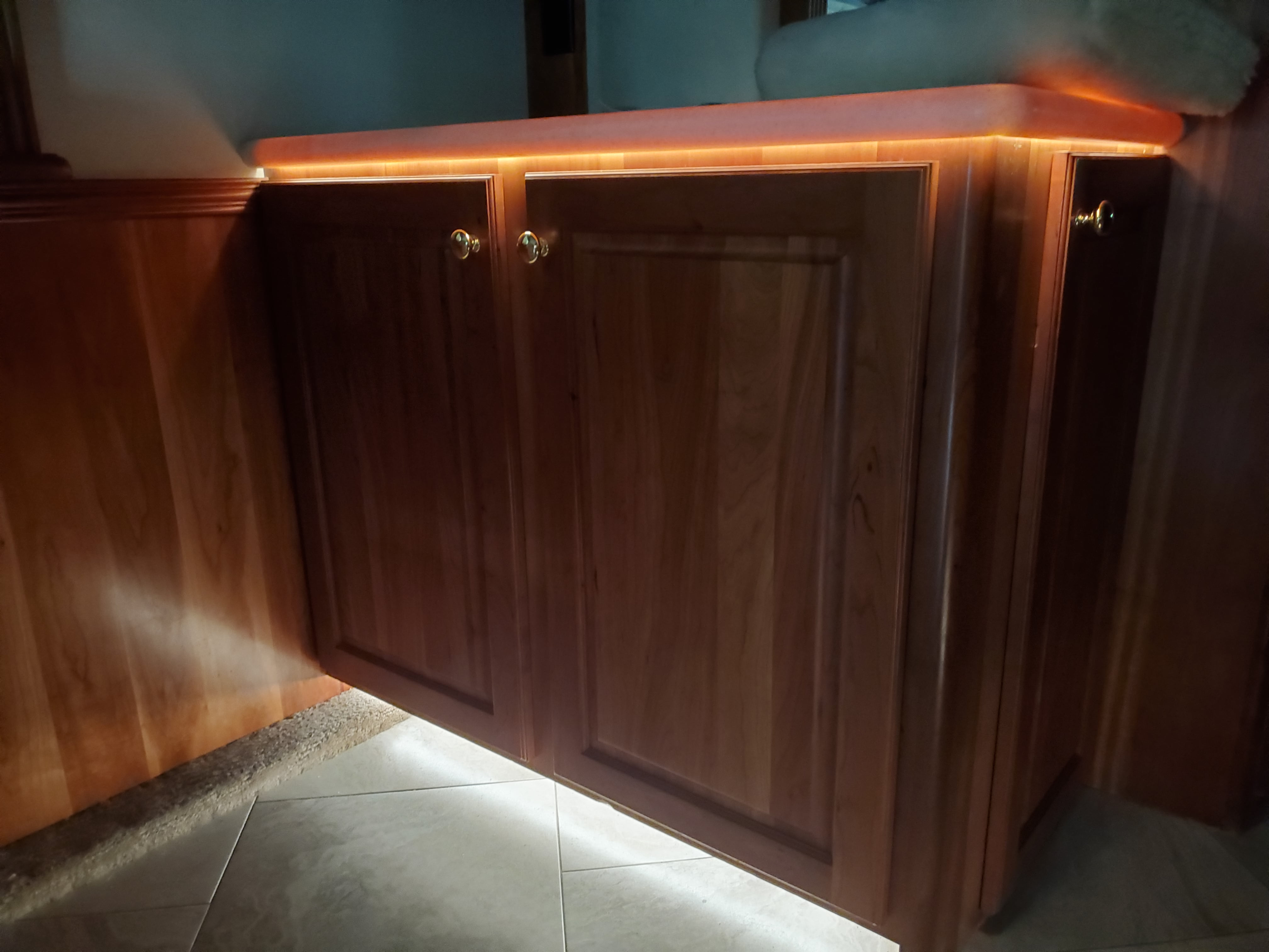
We had previously moved the toe kick lighting switch from the entry door to the kitchen as part of an earlier update. Now it was time to upgrade the floor (toe kick) lights and the under-counter lights.
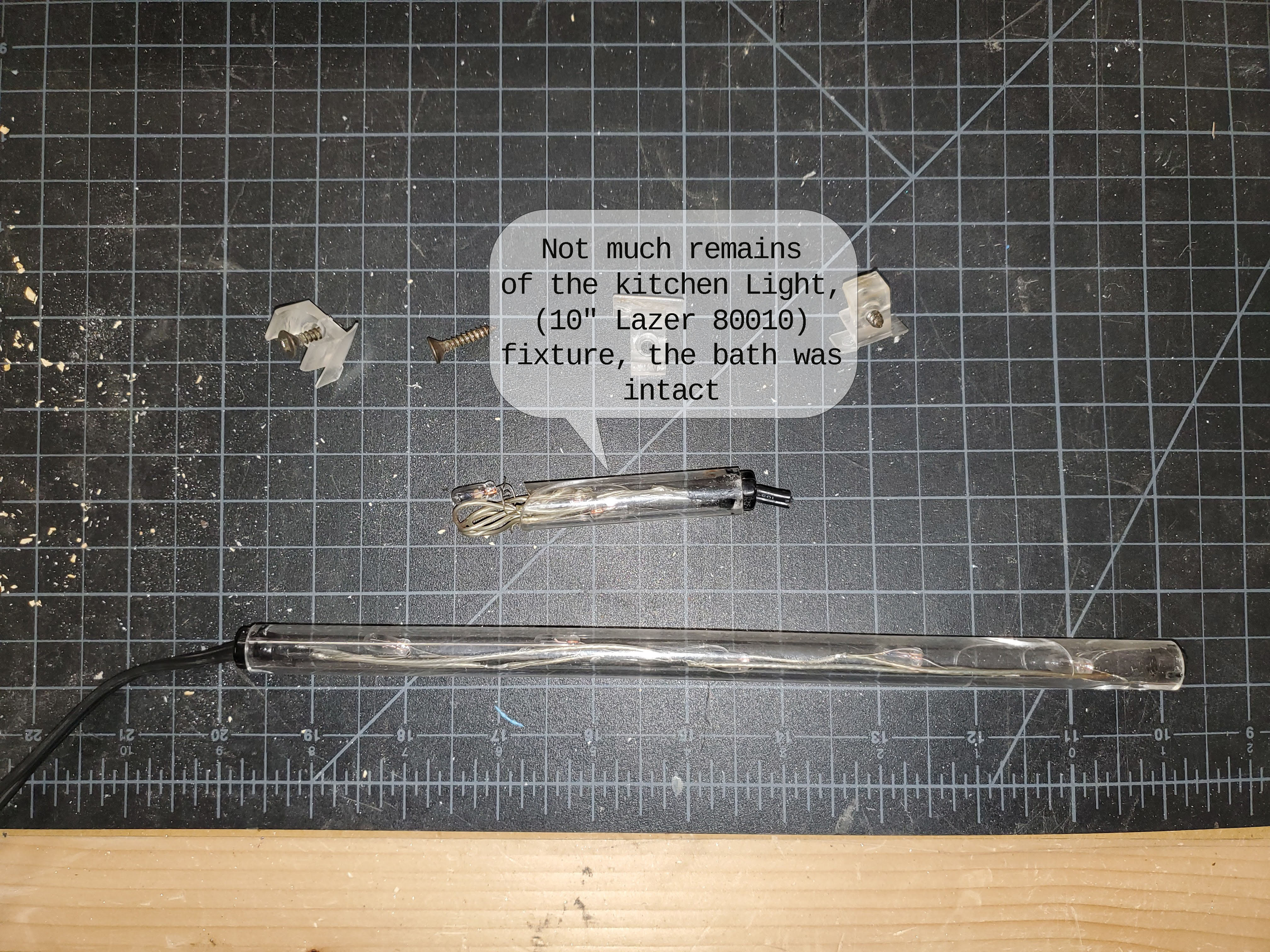
The floor lighting in the kitchen was completely non-functional, while the strip in the bathroom was still intact and working well. There was no toe kick lighting in the hutch/pantry area, so we wanted to add one there.
The under-counter lighting was mostly out, with only a few lights working. Lighting was present in the kitchen, bathroom, and hutch countertop areas.
Choose your parts
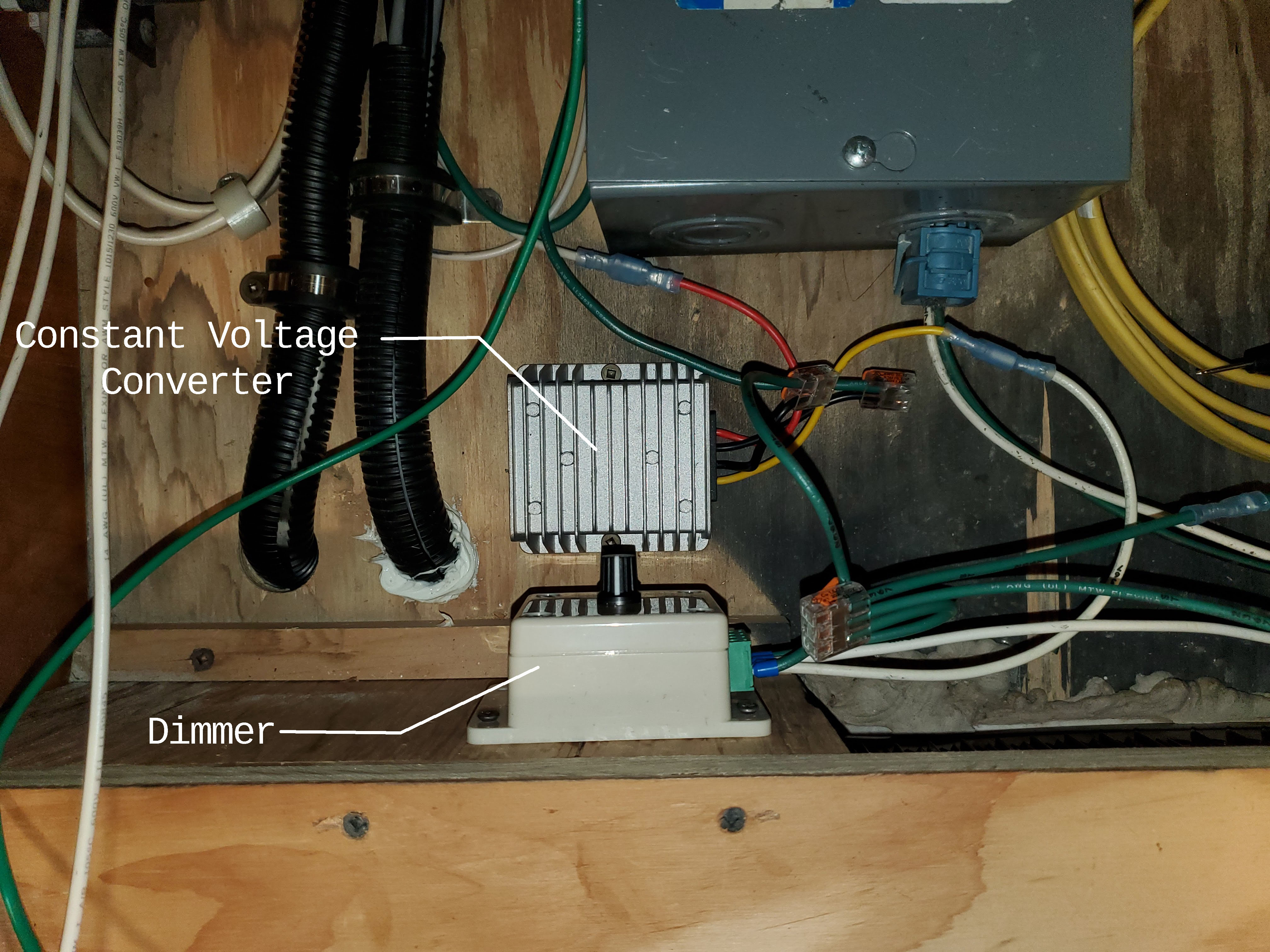
Yes, for the strip lights I used a constant voltage power converter that can step up or down the input voltage and provide a steady 12V output. Was it necessary? Probably not. Was it better? Yes. DWMYH
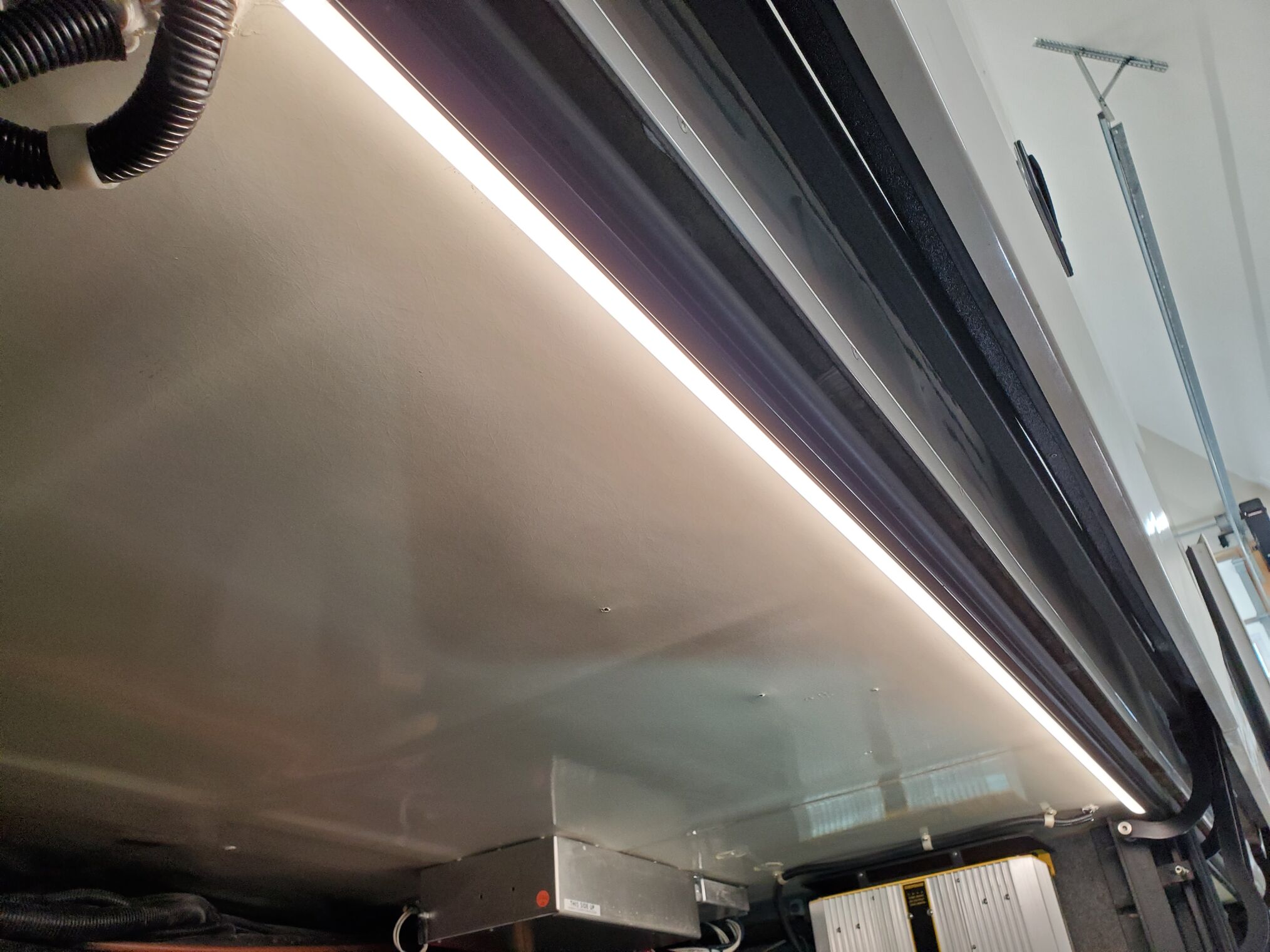
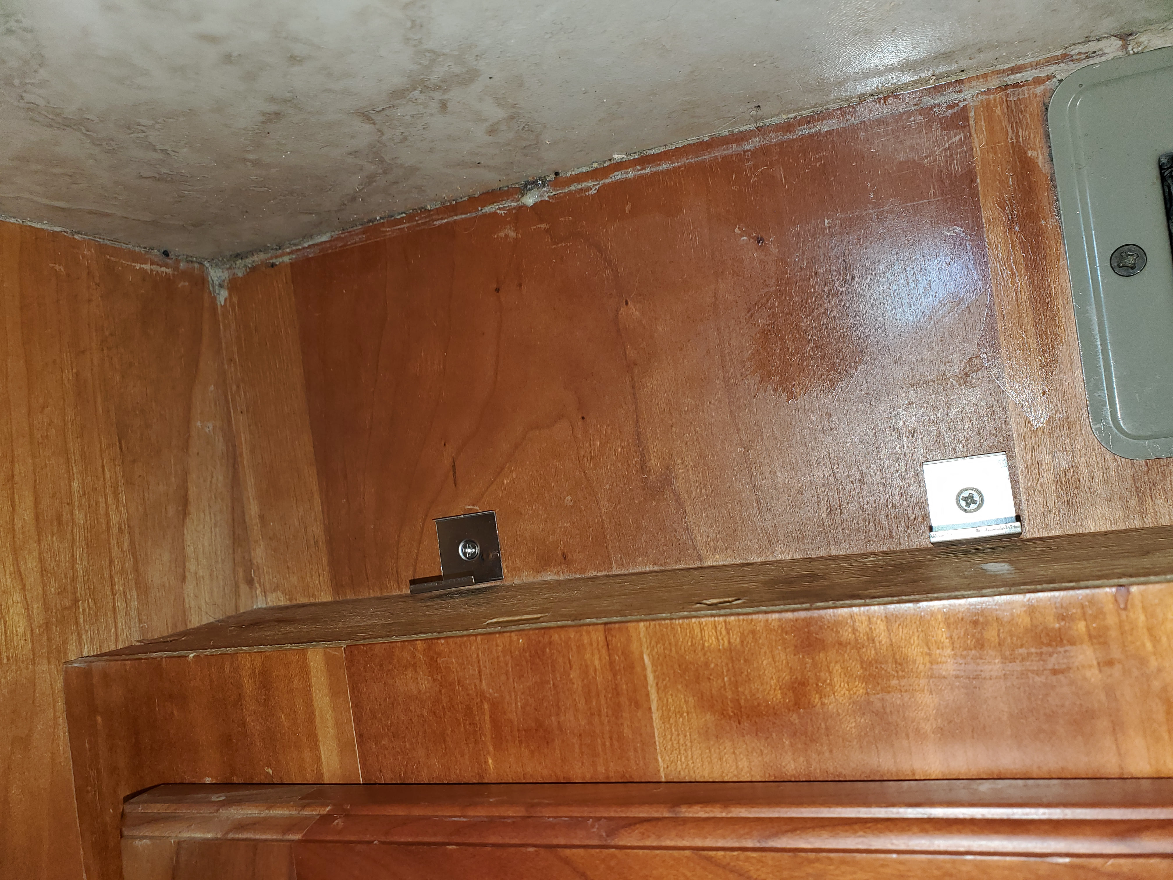
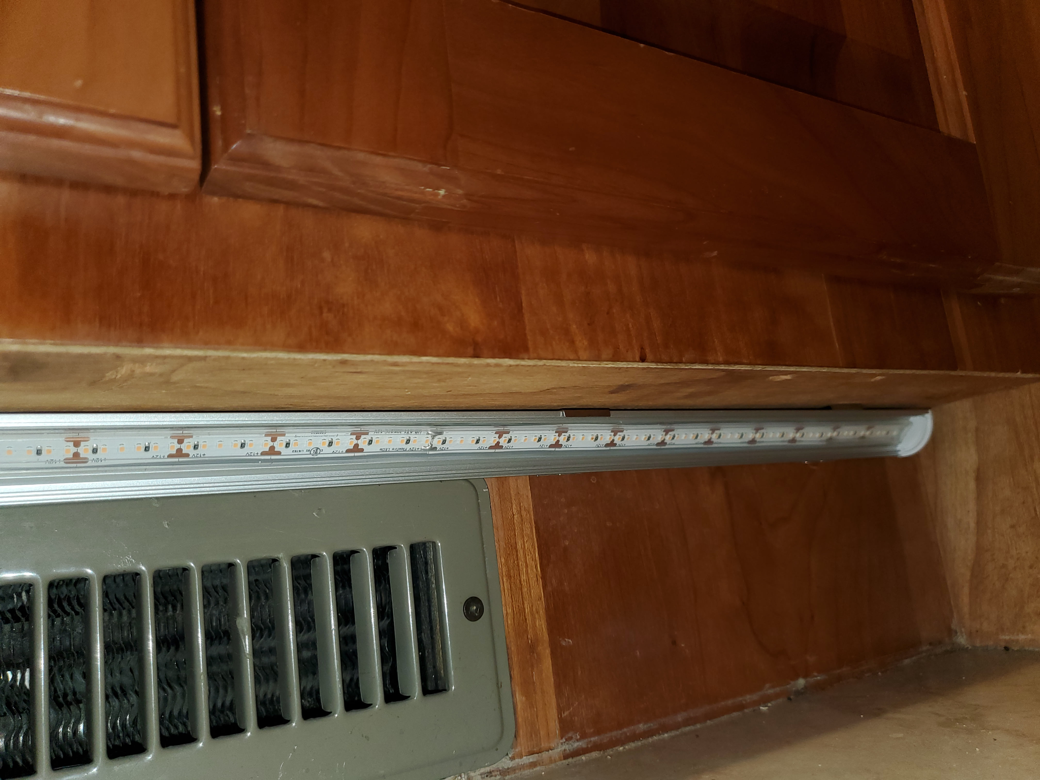
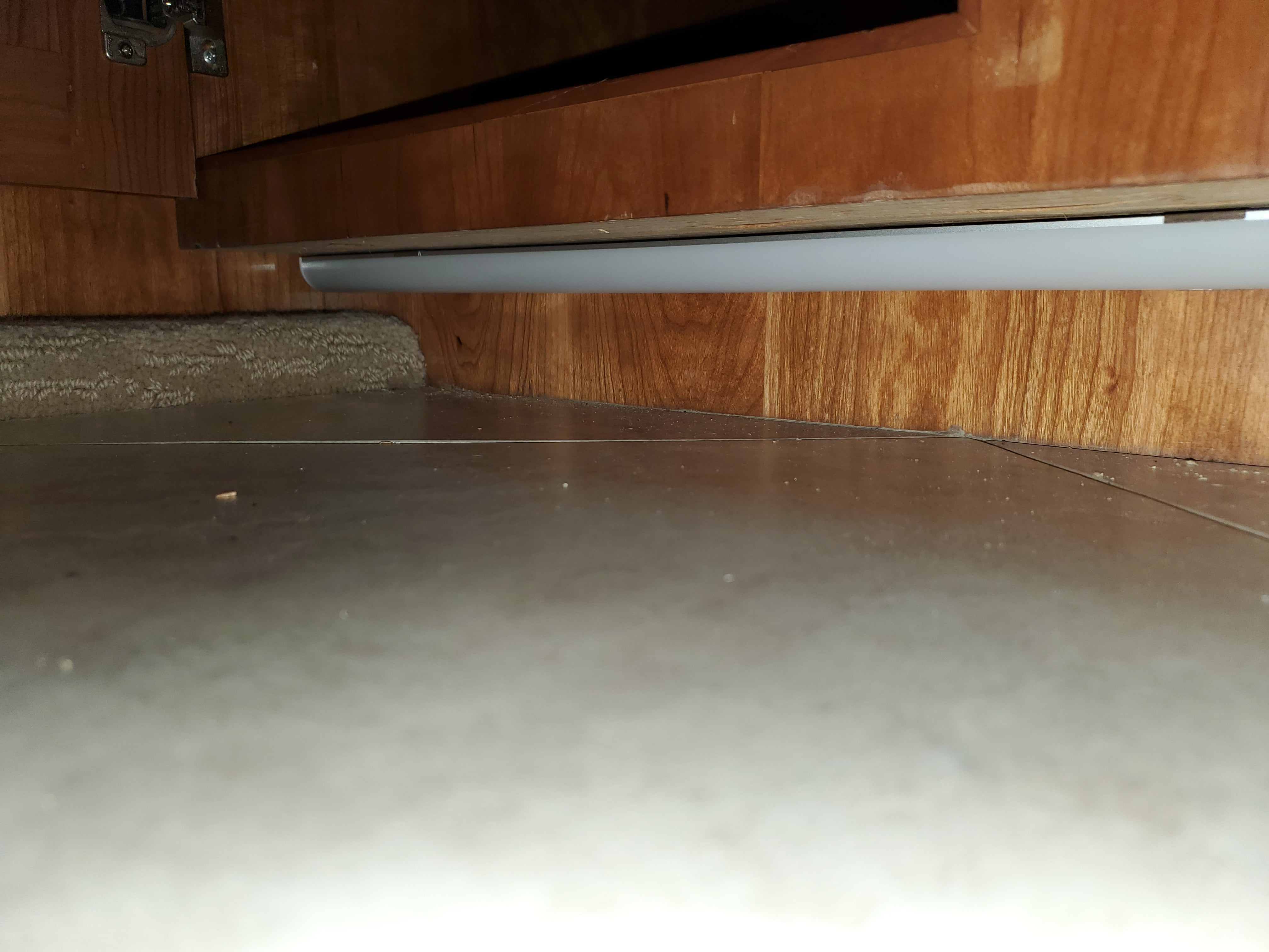
We used the same outdoor accent LED strip lights that we had installed in the storage bays. The strips were mounted using VHB tape onto aluminum angle brackets, which were then attached to the cabinets using the clips that came with the channels. We also added a frosted lens cover since this was meant to be accent lighting.
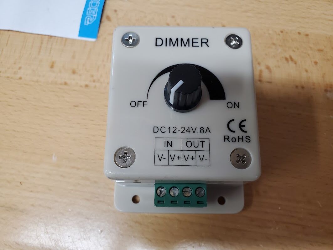
Even with the frosted lens and lower-brightness strip, the lights were too bright, so a dimmer was needed. We used a generic 8amp dimmer that worked well. Full disclosure: it’s since been replaced with something better, which I’ll cover in a future post.
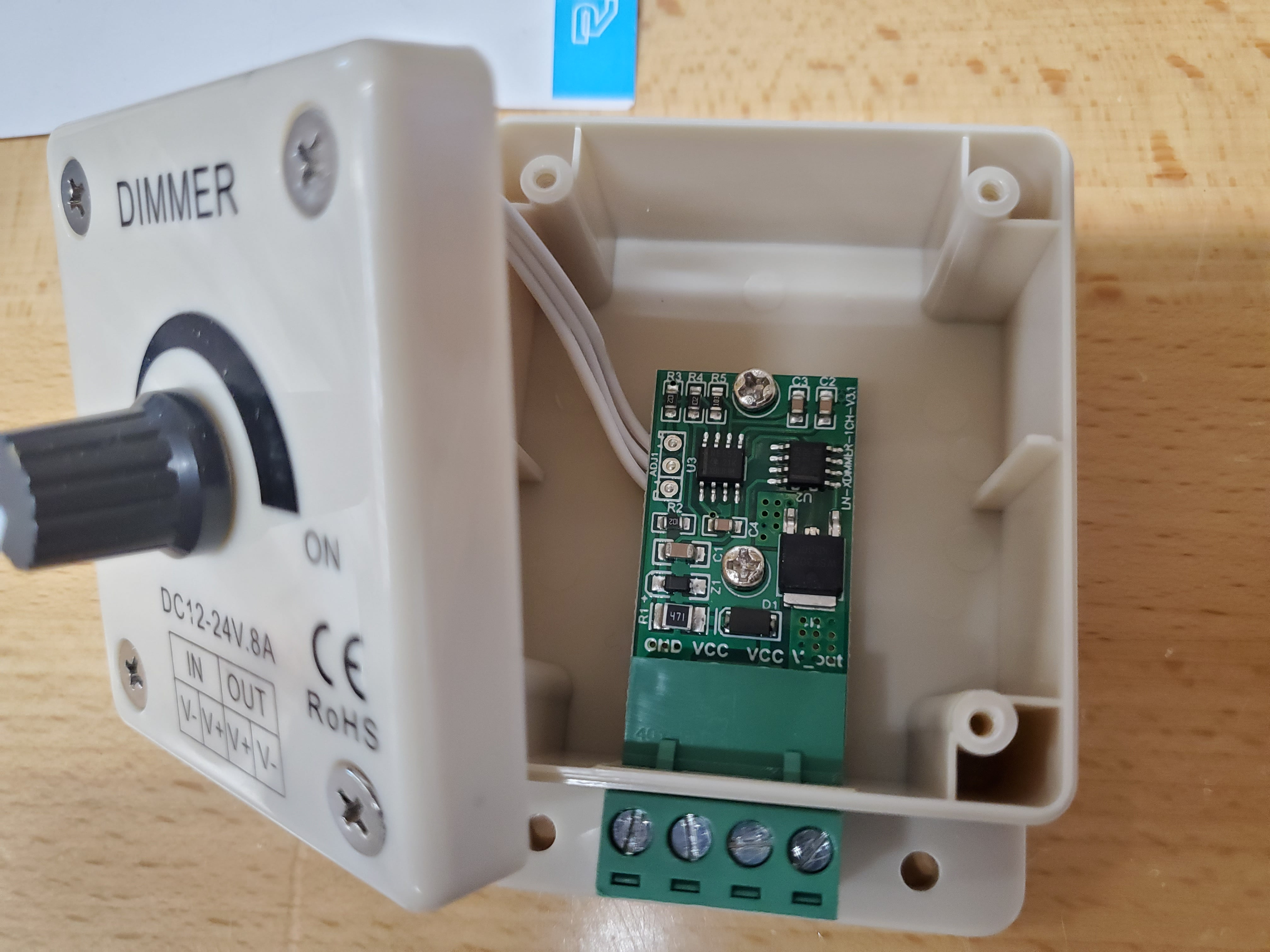
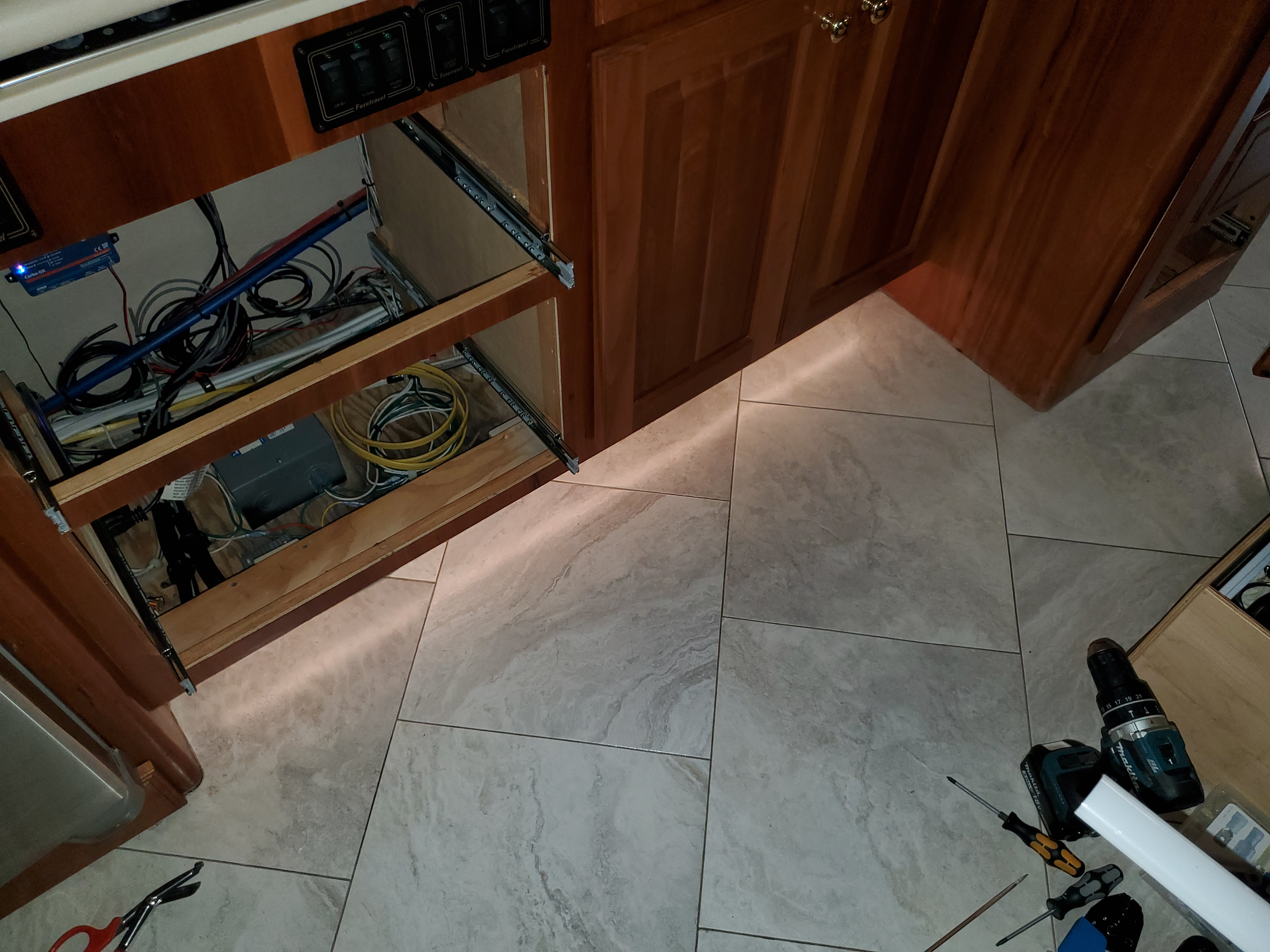
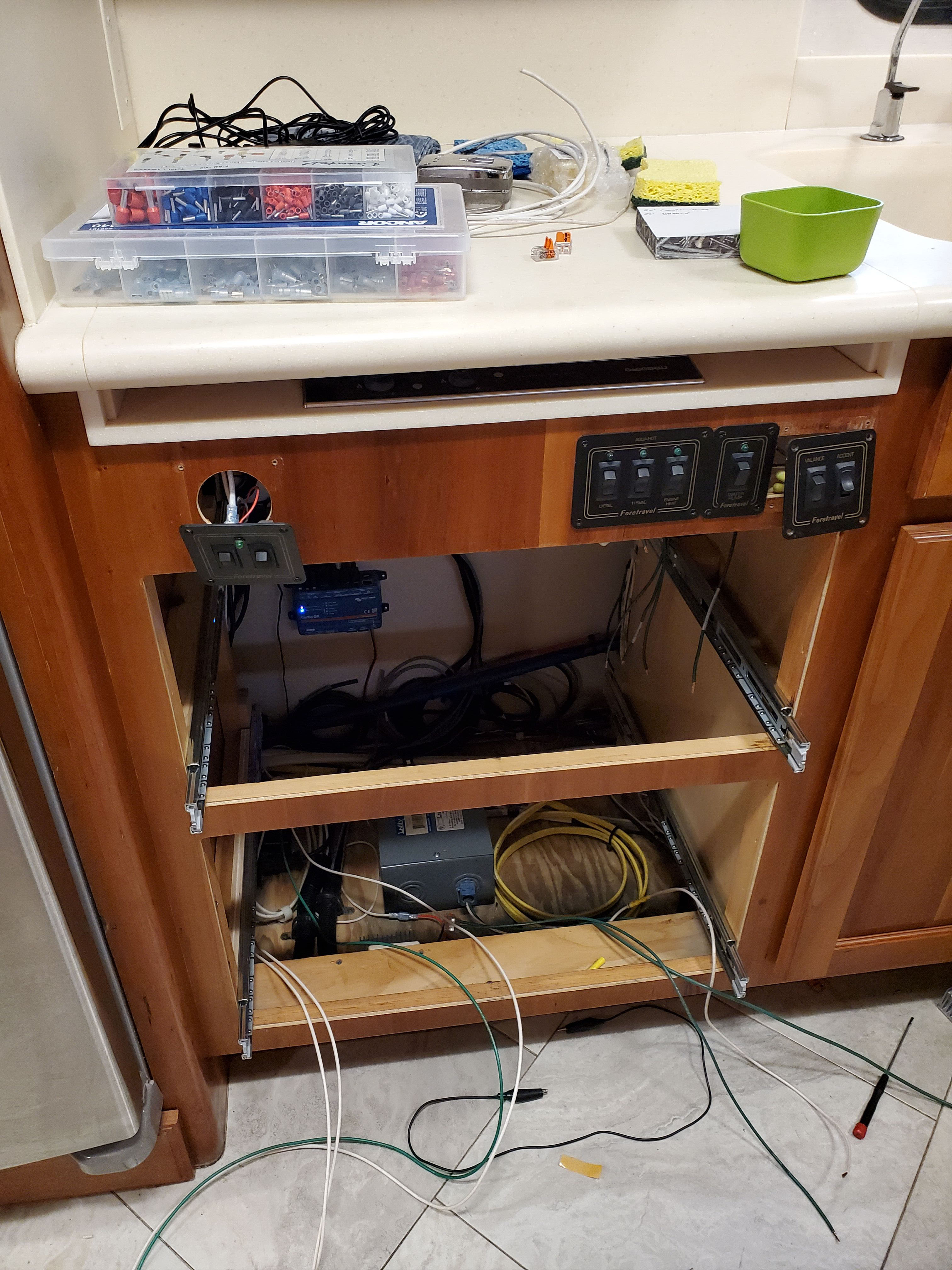
I didn’t have a good location to install the dimmer where it would remain easily accessible, so I mounted it underneath the kitchen drawers, assuming it would be a “set it and forget it” situation. This dimmer is available under several brands, and it looks like something out of the 80’s, but inside it has a somewhat modern solid state PWM.
Dimmer Side Notes
Here are a few notes on dimmers, at least as I understand them. There are two types: high-side and low-side.
-
High-side dimmers connect on the positive (+) side and control the flow of power into the load.
- Most high-side dimmers have 3 wires: an Input (+), Output (+), and a Ground (-) which is only required to power the dimmer itself, not the light fixture.
-
Low-side dimmers connect on the negative (–) side and control the return path to ground.
- Most low-side dimmers have 4 wires: (+)(-) Input and (+)(-) Output. Oddly, the two positive wires are typically just connected together inside the dimmer. That (+) is only required to power the dimmer.
Both types use PWM (Pulse Width Modulation). Which one you need (high-side or low-side) depends on your wiring and how your lighting is configured.
The dimmer I purchased turned out to be a low-side type. Here is another low-side example. At the time, I wasn’t aware of the distinction between high-side and low-side dimming.
A low-side dimmer references ground and requires full control of the ground path. If the negative sides of your lights aren’t all grouped with a single path common ground, you’ll end up on a frustrating wiring hunt. How do I know this? Because that’s exactly what happened.
A high-side dimmer wouldn’t have had this issue, as it controls the positive voltage going into the lights. You’d just place it after the switch. However, finding a high-side dimmer that isn’t integrated with its own switch seems to be difficult.
Two high-side examples that I found are from American Technology Components:
- AH-SLD-5-HS01
- AT-RLD-5-01 .. which is what we had in our LTV.
Back to the Lighting
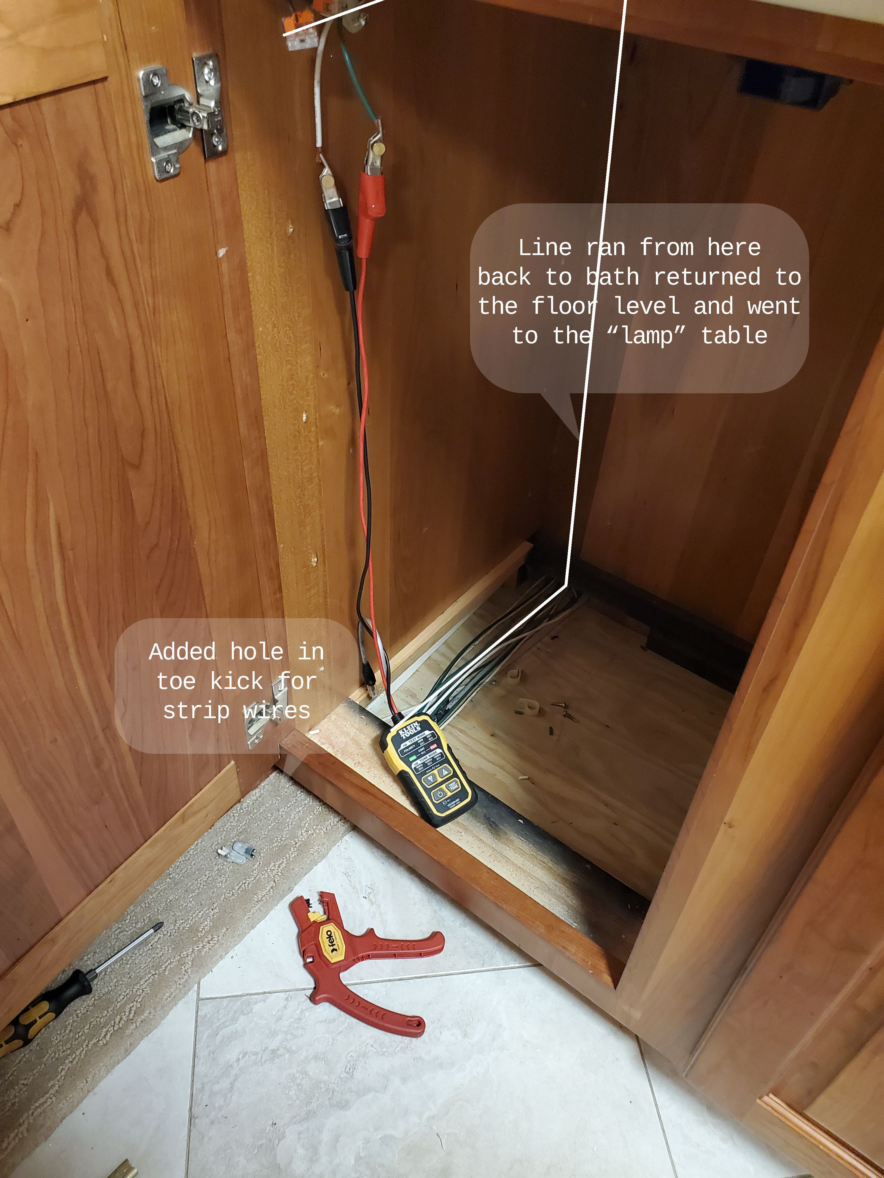
We ran two new wires from the bathroom sink cabinet to the kitchen sink cabinet. Since relocating the toe kick switch was a retrofit, the original power and ground junctions were located at the base of the bathroom sink. With the new switch now in the kitchen, we needed to adjust things accordingly. Fortunately, all grounds were grouped into a single return path, which made the low-side dimmer setup work perfectly.
Adding the toe kick light to the hutch was simple. There is already wiring in place running from the bathroom sink base to the hutch base. I just had to run two additional wires through the existing openings. In the base of the hutch, I drilled a small hole to feed the LED strip wire through.
Under-Counter Lights
Replacing the under-counter lights turned out to be a chore.
The original light strips had a P-shaped profile, with the lights embedded in the rounded part (the “O”) and fastened using staples along the straight edge (the “I”). These strips were installed before the countertop was added, which made removal awkward.
There’s no graceful way to get them out. You start at a free end, the one without any wiring, dig up an edge, and then… yank. You basically have to tear them out. The strips’ “O” blocks access to the staples, and even if you could reach them, the staples are longer than the gap where the lights fit, so removing them intact isn’t really possible.
After ripping out the strips, I went back and pulled the leftover staples. A screwdriver works to twist them out, or you can grab them with needle-nose pliers.
The old strips weren’t flexible anymore and had a greasy, oily film on them. That residue is likely old plasticizer leaching out from the PVC or vinyl casing — not something you want to handle too much. Wash your hands afterward, and maybe avoid licking your fingers :D
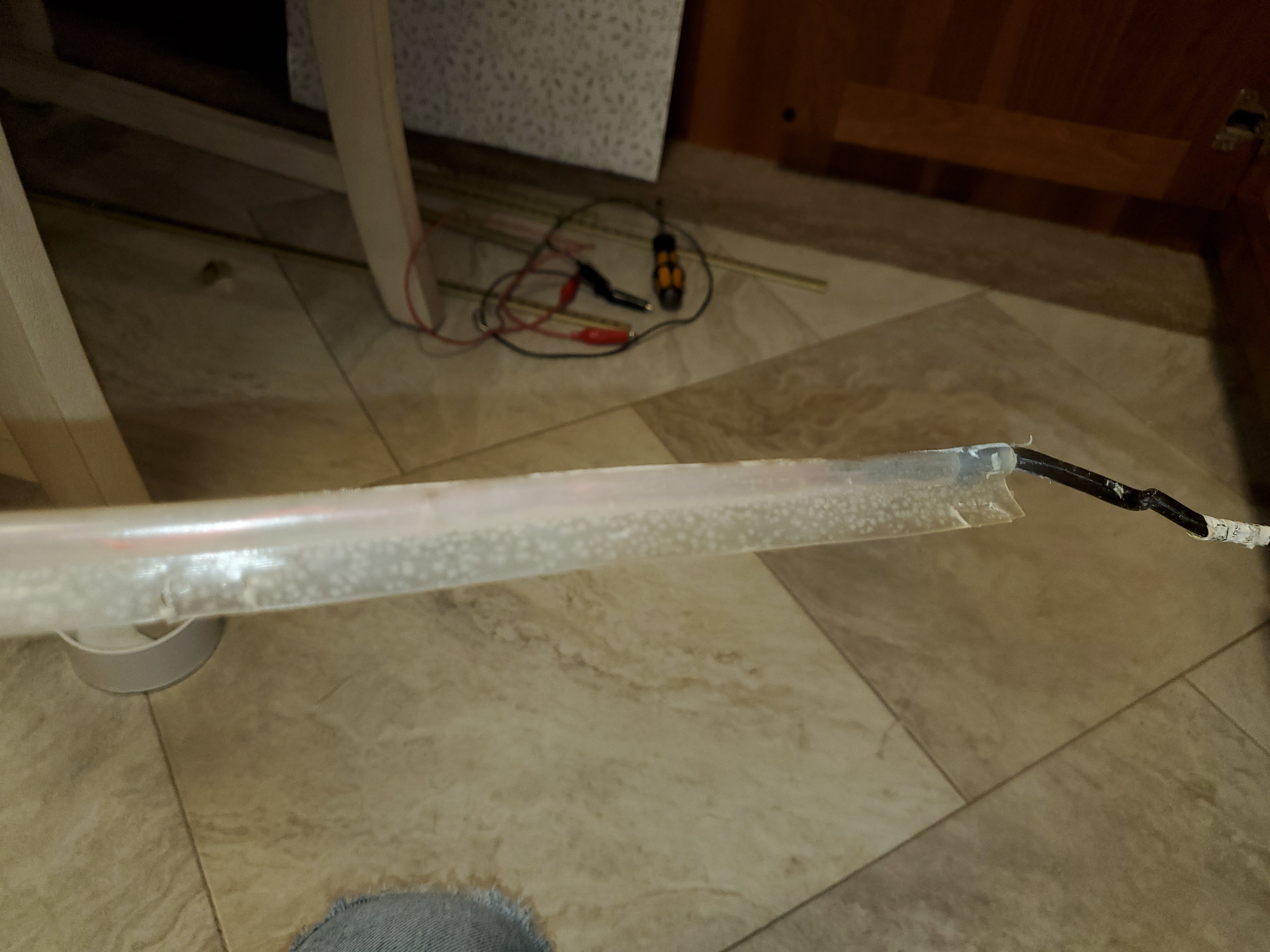
With the old rope lighting gone, we once again used the same LED strip lights we’ve used throughout the rest of the coach. These are housed in a silicone jacket, and the jacket comes with VHB tape on the back for mounting. The silicone jacket makes it easy to maneuver the strips into position, then press them into place to activate the adhesive.
I found that a body filler spreader worked well for guiding the strip, especially as the VHB didn’t stick (much) to the tool itself — this allowed for adjustments during placement.
Wiring Adventure
I thought I had a shared ground for the three countertop light strips. The kitchen ground was easy to identify, and there was a ground wire running from the hutch and bathroom cabinet lights back to the kitchen. So far, so good.
When I cut the first ground wire, the kitchen lights turned off; perfect. But when I cut the second ground, the bathroom and hutch lights stayed on. Grrr. That meant those two strips had another path to ground somewhere. Time to start the hunt.
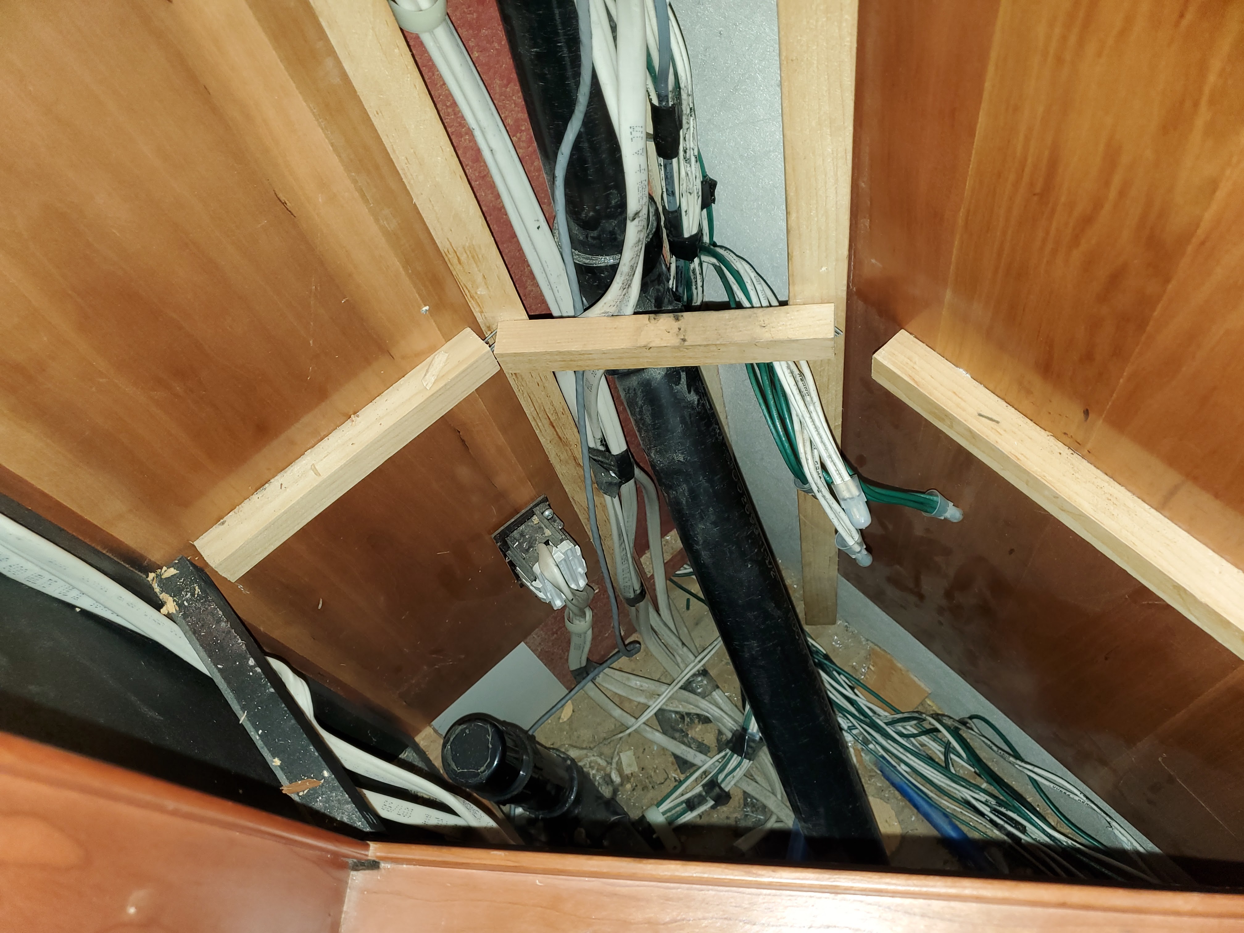
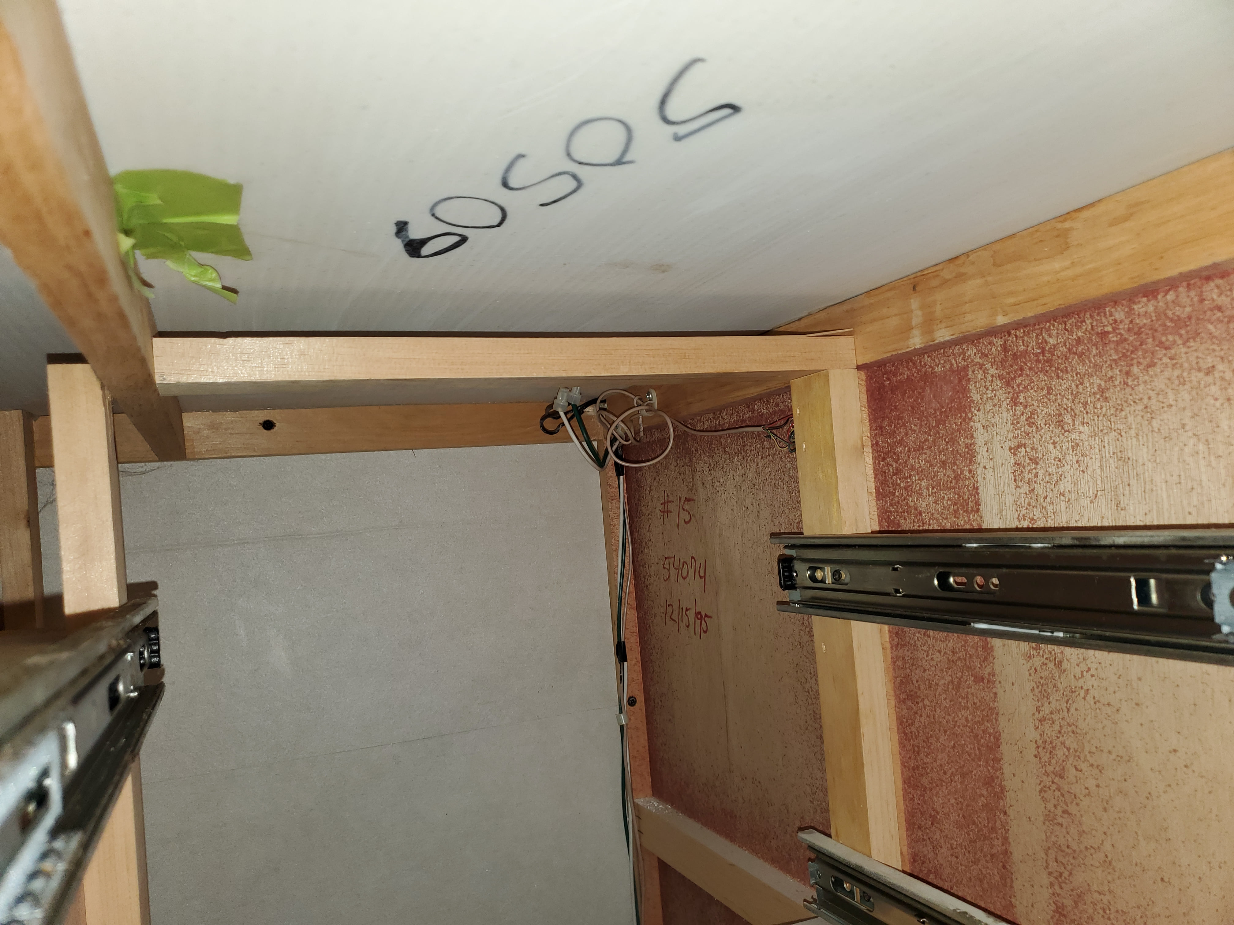
I traced the ground wire from the kitchen toward the bathroom, snaking behind and under the toilet and corner cabinet area. There’s a thick bundle of wires there, taped and clamped tightly to the floor in several places. Access was near impossible, and tracing was difficult because of all the wrapping and fasteners.
Eventually, I was able to follow the wire through the hutch area and back into the bathroom, looking for any splices that would have created an alternate return path. I found nothing obvious, no splices or unexpected junctions, so I kept tracing. I noticed the wire continued forward along the coach, running through the floor level raceway next to the outside wall. I was using a signal tracer, and the tone stopped near the table next to the recliner. Something was definitely going on there.
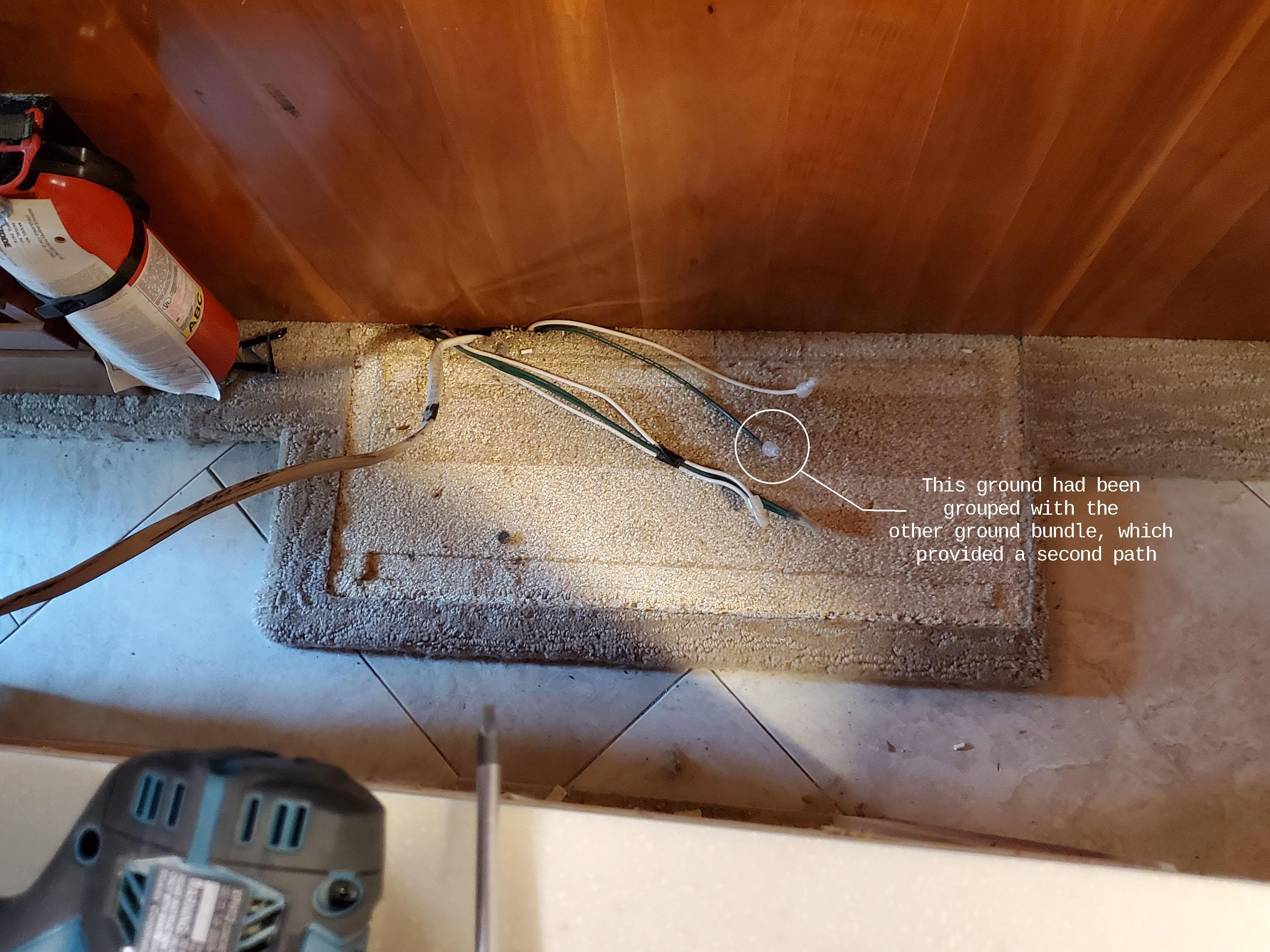
So I removed the table, and there was the culprit.
Apparently, the original tabletop must have had a built-in lamp and under-counter lighting. When that tabletop was updated, the +12V lines were properly capped, but the ground wires had been bundled together. That created a new ground path, which kept the bathroom and hutch lights powered even after I cut what I thought was the only return path.
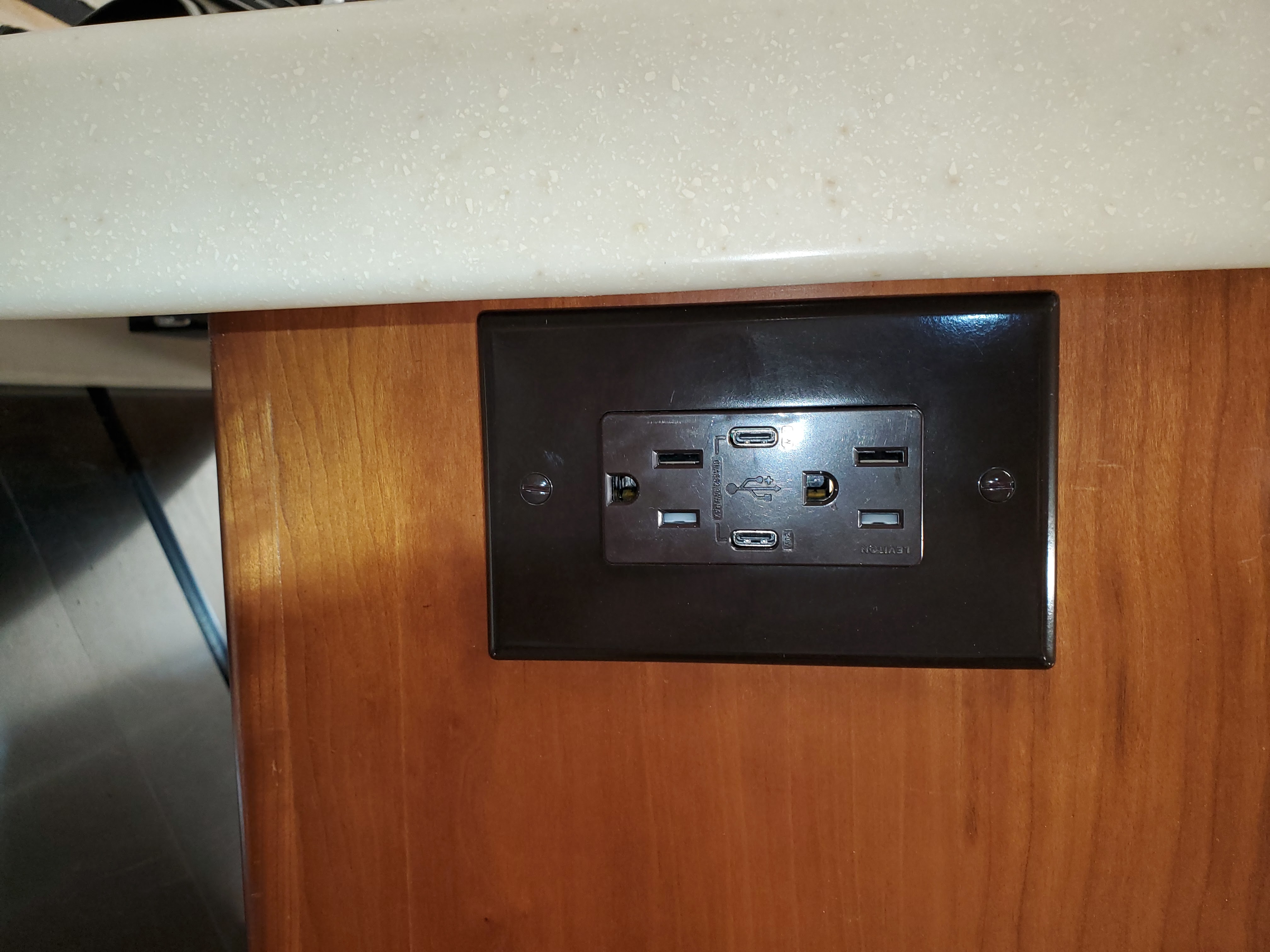
One quick snip, the extra ground was gone, and the circuit was clean and ready for low-side dimming. Since the table was out, I added a new USB outlet on the recliner side. It had an outlet on the other side but that was not terribly convient when you were in the recliner.
Only took disassembling half the coach to figure that out.
There is always one
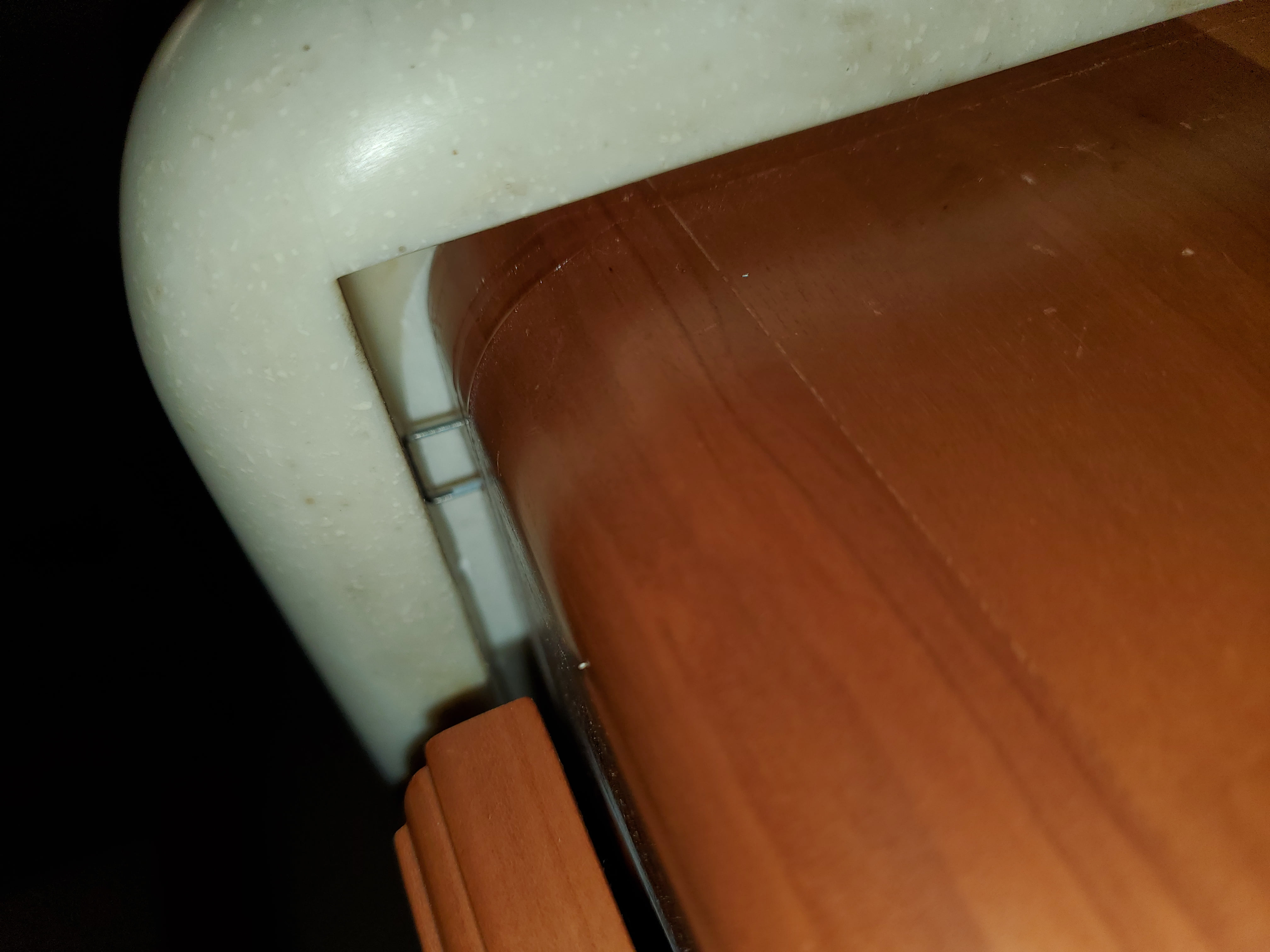
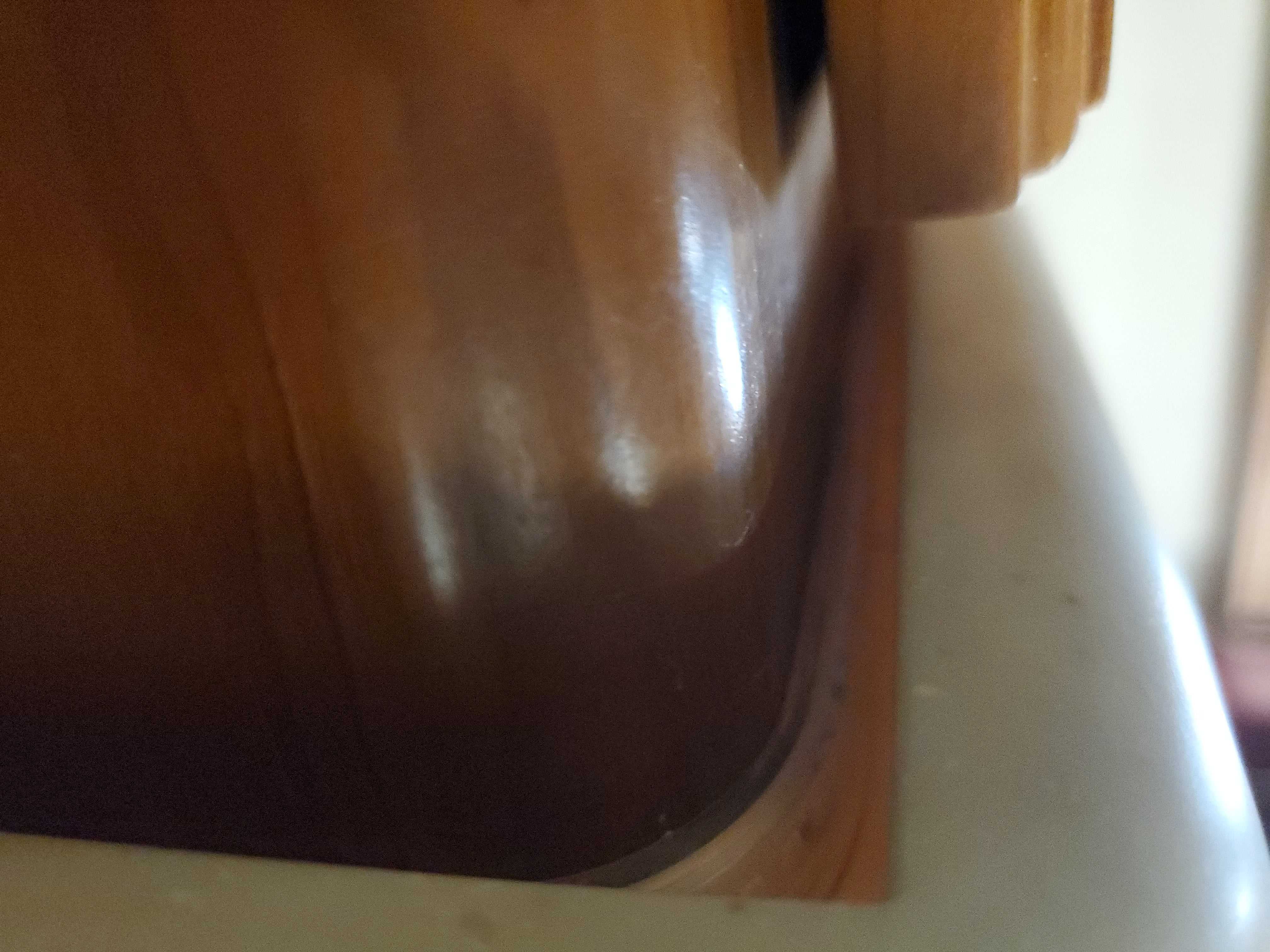
The under-counter lights in the hutch and bathroom were easy to wire, since you can access the strip-to-power connections from inside the cabinets. The kitchen, however, was a different story. The connection point was located in the far back corner of the peninsula cabinet, making it very difficult to reach.
The gap between the countertop and cabinet (in that area) is minimal, the LED strip just fits. The original passthrough hole was barely large enough to get a wire through. If I had realized all of this before adhering most of the LED strip, I would have cut the strip slightly short and tucked the connection into the gap alongside the strip itself.
Instead, I ended up having to enlarge the passthrough hole (long extension bit required, you have to do that from inside to outside) to fit a larger wire bundle. To keep the wires as small as possible, I soldered and heat-shrink-wrapped the connection, as wire crimps were still too bulky to fit. Another alternative would be to use a new long cable that you attach to the strip and make the connection back under the stovetop, that is where the current wires start from and that is more accessible. Anyway just something to keep in mind.