Adding a Victron IP22 Charger
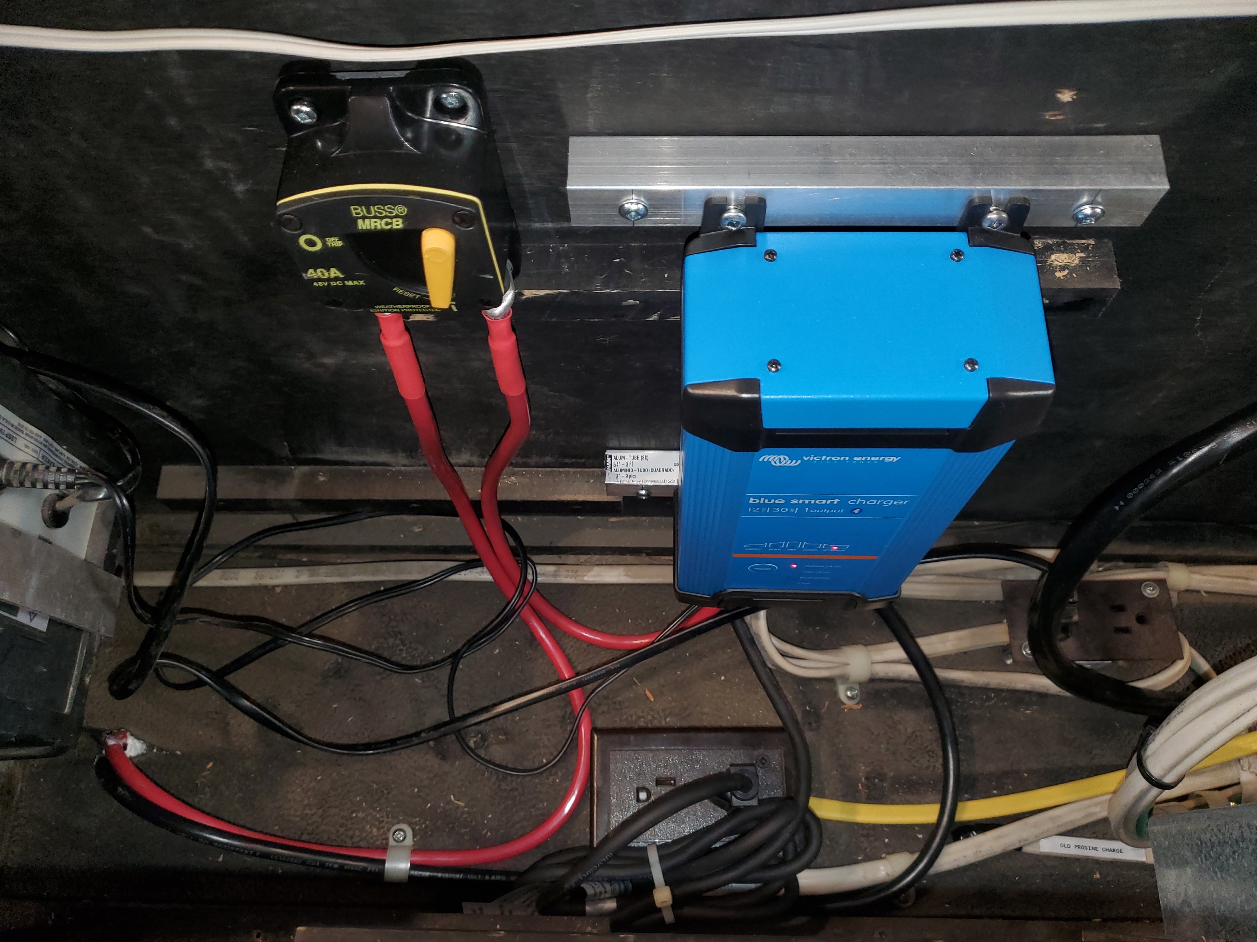
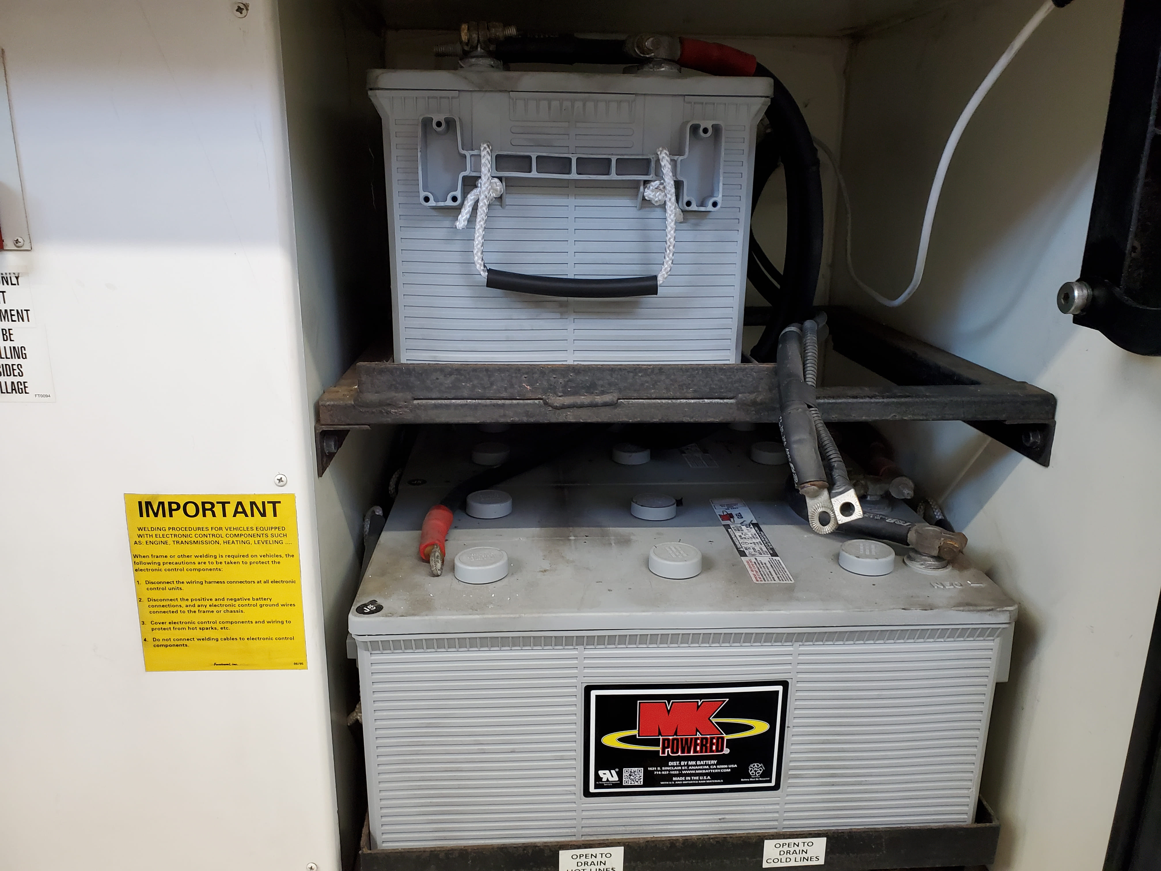
We added a Victron IP22 Blue Smart Charger to keep the chassis batteries topped up. It’s Bluetooth-enabled, so you can monitor and configure it through the VictronConnect app. Downside: no external data cable, so there’s no “official” way to tie it into the Cerbo.
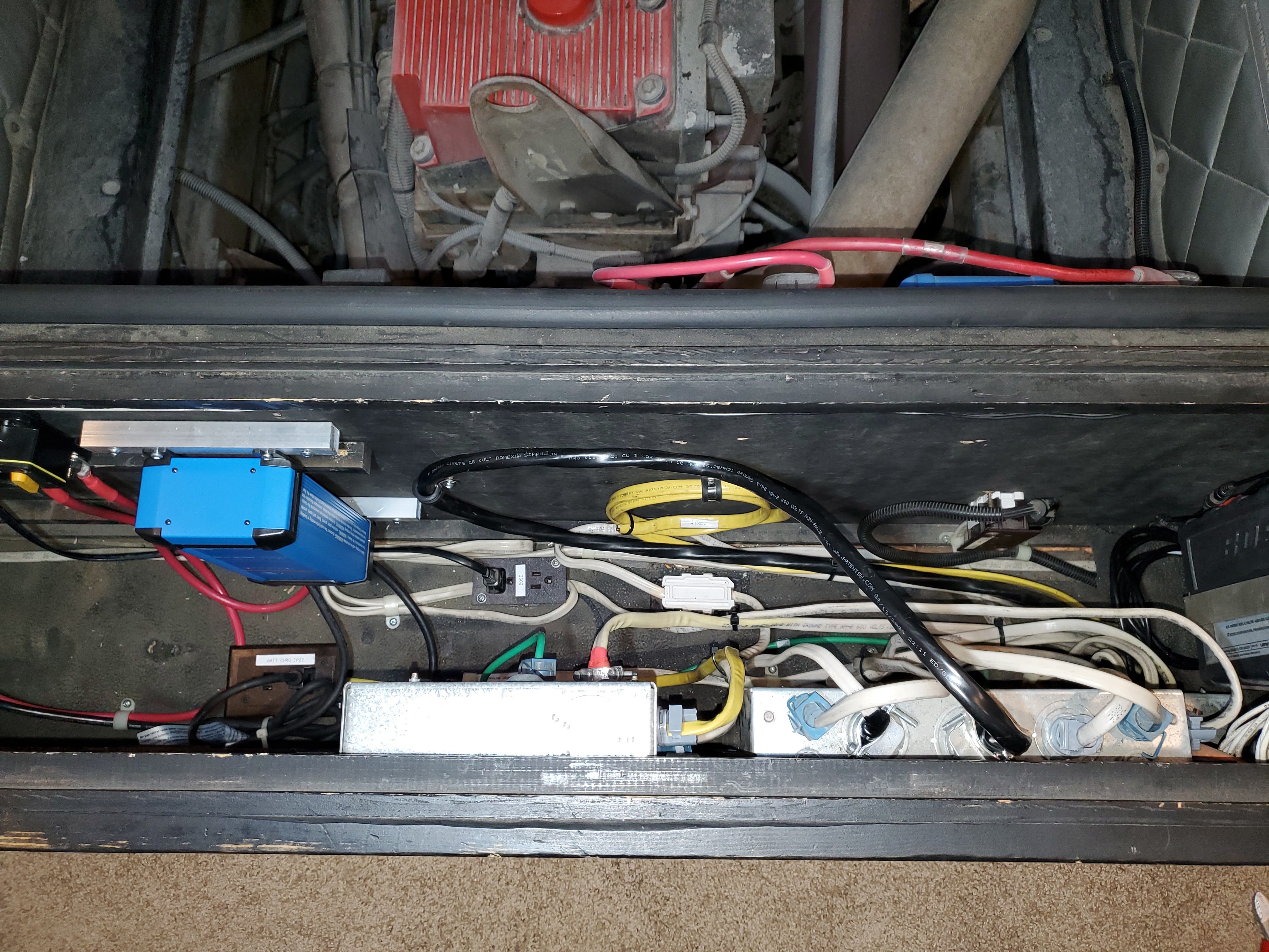
We mounted it in the compartment at the foot of the bed (lots of room in their after removing the two transfer switches and the Progressive EMS). The manual calls for a non-flammable surface, so I spaced it off the wall with a pair of aluminum channels which also provide for airflow. So far, it barely gets warm, though it’s only been needed for trickle-charging.
Its wired with #6 marine battery cable, which Victron rates for runs upto 5m. Its protected by a Blue Sea 187-Series Circuit Breaker victron recommends a minimum of 40A.
Two Challenges
There are two challenges to this setup that we wanted to address:
Preventing the Orion from unnecessarily enabling itself
When the IP22 is active, it can trick the Orion DC-DC into thinking the engine’s running. The Orion does have an enable jumper that you can wire to ignition, but instead I enabled the Venus Large OS on the Cerbo. That unlocks Node-RED and Signal K integrations. NodeRed is widely used in IoT integrations and is a visual, event driven, integration, which is perfect here:
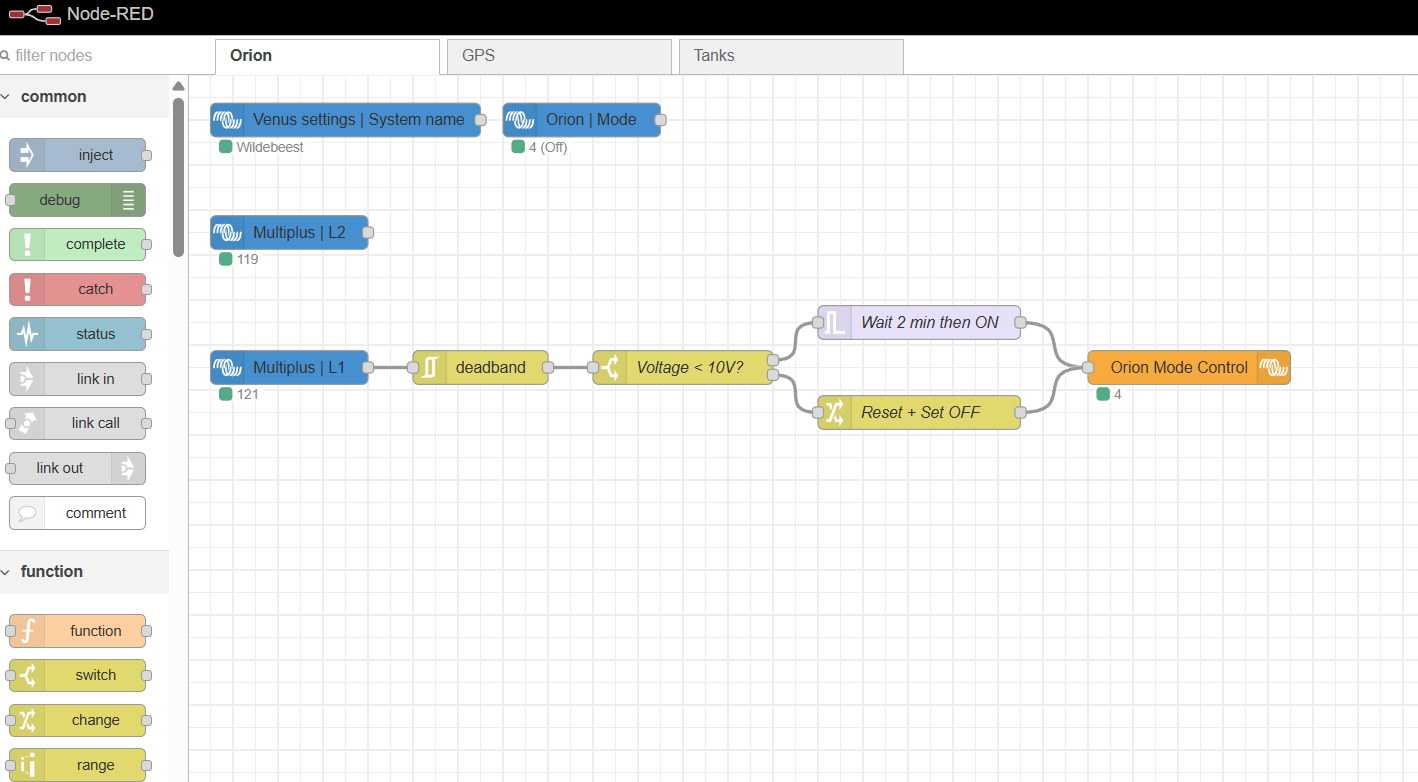
If Multiplus has AC → wait 2 mins → turn OFF Orion.
If Multiplus loses AC → wait 2 mins → turn ON Orion.
Simple. If we’re plugged in, there’s no reason to have the Orion running.
Avoiding a “Battery Loop”


We didn’t want: 12V house → inverter → 120V AC → IP22 → 12V → chassis. So we want to avoid trying to charge the chassis batteries via the house batteries when the system is inverting.
Options:
- Use one of the Cerbo relays + 120V switching relay at the IP22 outlet, controlled by Node-RED.
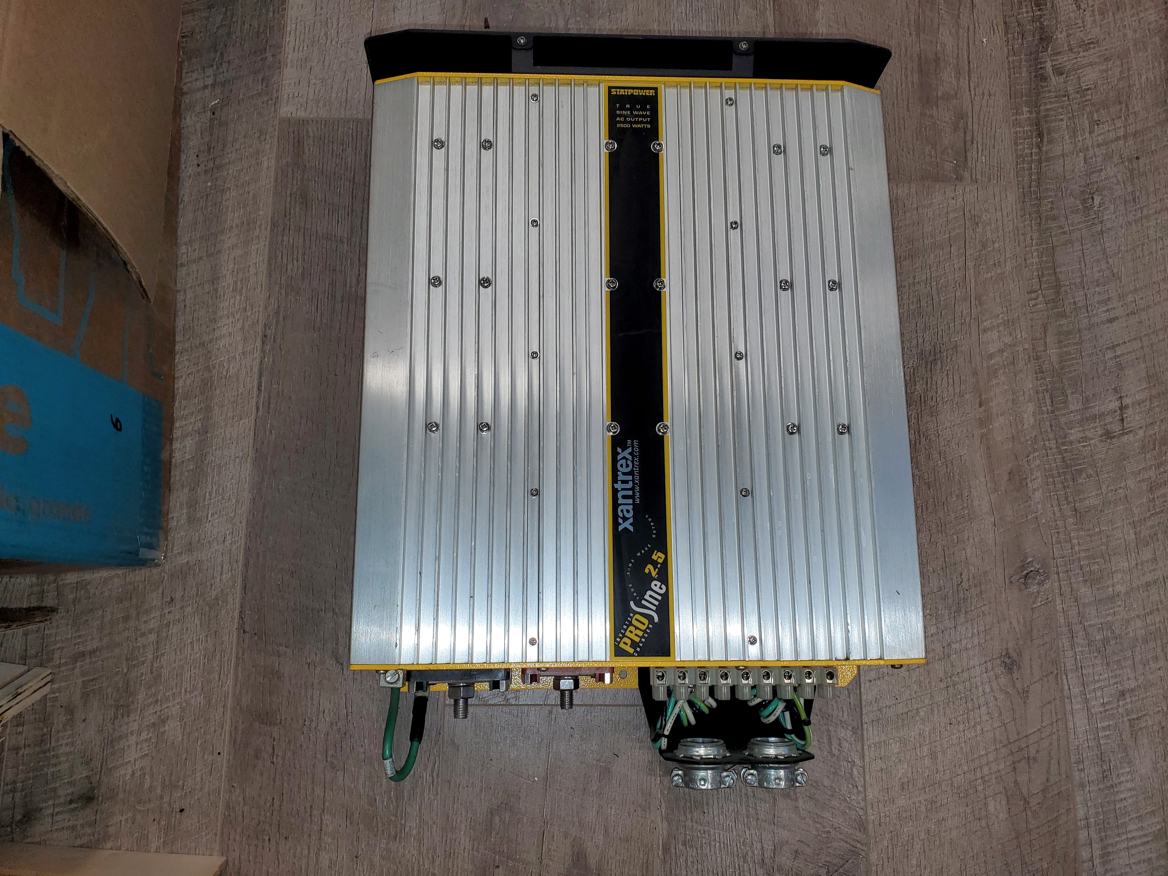
- Or… rewire the breaker boxes and make use of AC-OUT2 on the Multiplus.
We went with the latter, but not just to help with the charge issue.
Originally:
- Main panel = non-inverted
- Secondary panel = optionally inverted
Now:
- Main panel = Multiplus AC-OUT1 → inverted (UPS + power boost support)
- Secondary panel = Multiplus AC-OUT2 → not inverted, only hot with shore/gen AC
That means the IP22 (on the secondary panel) only runs when the coach has AC input. We also moved the engine block heater and AquaHot to that panel / AC-OUT2.
Extra Notes
- Reused the original 10/2G Romex from the old Prosine → old transfer switch(2). In hindsight, I should’ve replaced that 10/2 with 10/3 (or bigger) for flexibility. Now that original 10/2 runs from the Multiplus AC-OUT2 → secondary panel main breaker.
- Swapped the secondary panel main breaker from 50A to 30A (#10 wire rated). Foretravel originally used a 50A since transfer switch 2 could have been feed from the Prosine 10/2 or shore 6/2. Later models moved to 40A. Either way, a compromise, but now protection matches the wire.
- Since the 10/2 only carries a single hot, all secondary panel loads must sit on either L1 or L2. That’s up to you, choose based on load balance. On our year coach, everything in that box was on L2 FWIW.
Updated Schematic
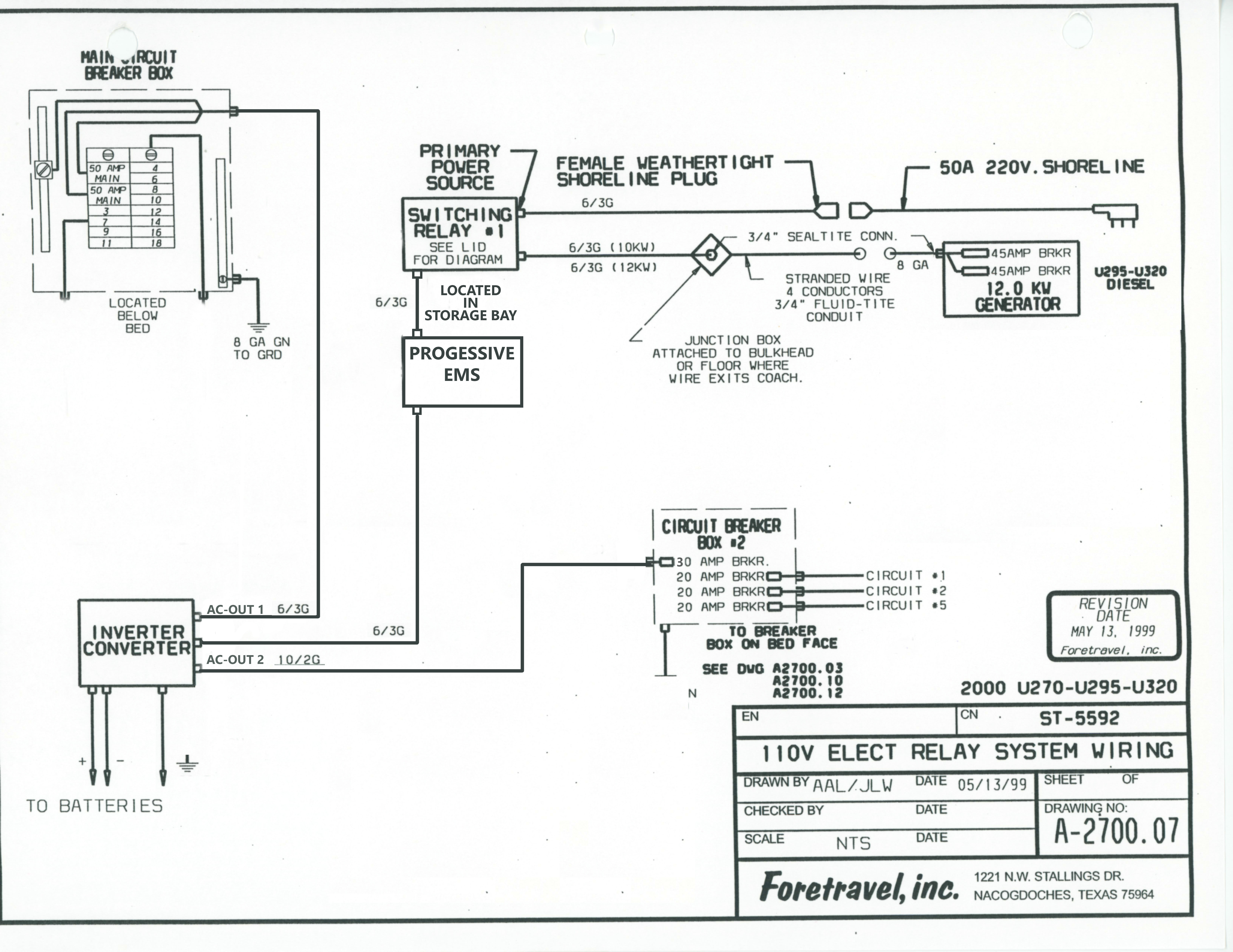
I did a quick update to the schematic to reflect the new setup.